
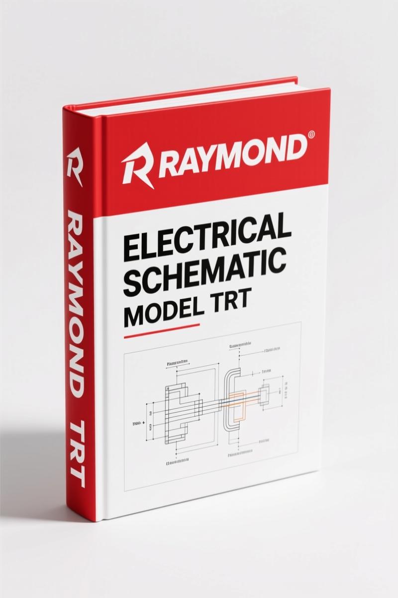
Raymond TRT 2010 Electrical Schematic – OEM Wiring Manual (15 Pages)
Original price was: $18.14.$14.99Current price is: $14.99.
OEM Raymond TRT 2010 electrical schematic – 15 pages of factory wiring diagrams, connector callouts, and diagnostic references for certified technicians.
Description
Raymond TRT 2010 Electrical Schematic – What You Get for 15 Pages
If you have ever chased a ghost in a Raymond TRT reach truck with a generic wiring diagram that showed six different wire colors for the same circuit, you know why this Raymond TRT 2010 Electrical Schematic matters. Fifteen pages, no guesswork, and every connector pin named exactly as Raymond printed it on the line. I have been turning wrenches for 28 years and I still refuse to diagnose electrical faults on any lift truck without the OEM schematic in hand. Aftermarket copies drop details – they lose the test point voltages, they drop the sensor ground references. This one does not.
Raymond TRT 2010 Electrical Schematic: Exactly 15 Pages of Factory Wiring
Each page in this 15-page schematic is a full-size factory foldout, printed on durable paper that survives grease and coffee. The first sheet covers the fork load handler electrical system – contactor panel, motor velocity sensor circuits, motor temperature thermistors, and the primary control handle wiring. Page 1 alone shows the TP1–TP5 test points, the three fuses (150A, 500A, 350A), and the STR, LPC, TPC contactor coils. If you have ever had a truck that would not move and you suspected the STR–2 contactor, you can probe exactly at TP4 and verify coil voltage without flipping through three different diagrams.
Raymond published this on July 1, 2010 under publication 1123027A. It applies to serial numbers TRT-03-00100 and up. That date matters – earlier schematics used different pinouts on the JPC connectors. This one also references the maintenance manual PDMM-0092D for mechanical procedures, so you keep both in the truck. The schematic alone will not tell you how to remove the drive motor, but it will tell you exactly which wire is L VEL PHASE A and where it lands.
Why Pull a Factory Schematic Instead of a Generic Wiring Diagram?
A generic diagram might show a contactor coil as a rectangle. This Raymond schematic labels every coil terminal: STR-2, MS A2, LPC, TPC. It marks the microswitch contacts inside the primary control handle – P_THROTTLE, P_HORN, LIFT, REACH, RETRACT, TILT UP, TILT DOWN, SSHIFT LEFT, SSHIFT RIGHT. You need to know that the H_HTR wire is a separate circuit for the heater, not part of the travel interlock. The generic diagram will lump it all into one block labeled “handle assembly.” That is how you spend an hour probing the wrong connector.
I have seen techs skip the OEM schematic because they thought the 15 pages looked confusing. Then they replace three contactors because they didn’t read that the LPC coil gets its 12VP from JPC20-8, not from the same bus as the STR coil. A schematic is a map – you don’t drive a blind intersection in San Antonio without a map, and you don’t diagnose a dead Raymond TRT without this one.
Where to Find the TP1–TP5 Test Points
Page 1 of the schematic shows TP1, TP2, TP3, TP4, TP5 laid out on the contactor panel. TP4 is the test point for the STR contactor coil voltage. TP5 feeds the LPC and TPC coils. If your multimeter reads battery voltage at TP2 but nothing at TP3, you know the 150A fuse is open. The schematic also shows the motor velocity sensor (T VEL SENSOR+, ID2, T VEL PHASE A, T VEL PHASE B) with their pin numbers at the JPT2 and JPT3 connectors. When I see a “velocity fault” code, I go straight to JPT3-2 for T VEL PHASE B. If the waveform is missing, I work back to the sensor. That sequence is printed on the page – you do not guess which pin.
For the lift motor, the schematic includes the motor temperature circuit (T TEMP+ at JPT3-16, T TEMP- at JPT3-17). A cold solder joint on JPT3 can cause a thermal cutout that makes the lift stop intermittently. You would not find that detail in a reprint.
3 Key Sections for Diagnostic Troubleshooting
The 15 pages break into three main areas: fork load handler electrical (sheet 1 of 6), drive motor velocity and temperature circuits, and the primary control handle interface. Each section has its own connector callouts – JPS1, JPC12, JPC14, JPC20, JPC22, JPC24. The schematic lists every signal: BUS 1+, BUS_I, DGND, +12VP. The “Sounder” circuit (B-1, B-2) is separate from the “Alarm” output – Raymond labels them differently because one is a continuous tone and the other is a pulsed horn. Knowing that difference before you order parts saves you a return trip to the dealer.
If you see a fault code related to “HGG” (handle grip group), the schematic shows HGG CNTRL PWM on JPC24-12, HGG FAULT on JPC22-7, and HGG CONTACTOR on JPC24-2. You can backprobe these pins with the truck running and watch the PWM duty cycle. The factory schematic gives you the pin numbers and the signal names. You match them against a oscilloscope reading. That is how you find a broken wire inside the handle before you replace the whole assembly.
Who Needs This Raymond TRT Schematic?
If you maintain a fleet of Raymond TRT narrow-aisle reach trucks, you need this for every electrical diagnosis. It also works for home garage enthusiasts who bought a TRT at auction and want to bring it back to life without replacing every harness. I have seen people wire a new control handle by matching colors from a generic diagram – then the reach moves when it should tilt. That is a safety hazard. The OEM schematic shows the actual function of each wire, so you don’t cross the throttle with the horn circuit.
Beginners: start by locating the battery positive (B+0) and battery negative (B-K3) on the contactor panel. Then find the +12VP bus on JPC14-5 and JPC20-8. That is your power source for the controllers. From there, trace the DGND points – there are multiple returns, not a common ground. The schematic marks them: DGND at JPC24-23, JPC6-6, JPC14-10, and JPC22-1. If your meter shows voltage drop between two DGND pins, you have a corroded ground bus. That is a ten-minute fix if you know where to look.
Source Authenticity: Raymond OEM vs Aftermarket Copiers
This is a direct scan of the original Raymond publication 1123027A, issued July 1, 2010. The Raymond Corporation authorizes this document for use with maintenance manual PDMM-0092D. Aftermarket versions often re-draw the schematics from memory or from a low-resolution copy, which shifts component labels and changes fuse ratings. I have seen a reprint that listed the 150A fuse as a 250A – that could melt a cable during a stall test. The OEM print retains the exact font, line weights, and spacing that Raymond uses in their own factory troubleshooting courses.
If you order a reprint from a third-party, you risk getting a version where the “T VEL PHASE A” line is mislabeled as “T VEL PHASE B” because someone guessed. This manual does not contain those errors. It is the same print a Raymond dealer uses. For more electrical schematics on other Raymond models, check the Raymond 111, 112, 113, 114, 11XD 2010 Electrical Schematic – OEM Factory Wiring for similar narrow-aisle trucks. The Raymond 111 112 113 114 2010 Electrical Schematic covers those models separately. If you work on the heavy-duty 440C/470C series, the Raymond 440C/470C Electrical Schematic 2010 has its own layout. For general wiring theory, the Automotive Wiring guide from a trusted source explains the fundamentals. You can also reference the Automotive Industry Overview for context on how OEM documentation standards protect technicians.
- Will this schematic show me the hydraulic pump motor circuit?
- This covers the electrical connections for the fork load handler, drive motor, and control handle. The hydraulic pump motor is part of the body harness – the contactor panel includes the LPC and TPC contactors that command the lift and travel pumps. The schematic shows the power and feedback circuits for those motors, including motor temperature and velocity sensors.
- Does the 15-page PDF include wiring for optional accessories like side shift or fork positioner?
- Yes. The primary control handle wiring includes SSHIFT LEFT, SSHIFT RIGHT for side shift, and the TILT UP / TILT DOWN circuits. The schematic also has a “DUMP” circuit and an “AUX1 / AUX2” pair for additional hydraulics. If your truck has a fork positioner, it will connect through those auxiliary pins. The manual covers all options available for the TRT as of July 2010.
You want to get this wiring correct before you connect a replacement controller or splice into the harness. Access the Factory Manual from AutoRepairManuals and keep it in your truck – it pays for itself the first time you avoid a misdiagnosed contactor.
Additional information
| Brand | Raymond |
|---|---|
| Language | English |
3 reviews for Raymond TRT 2010 Electrical Schematic – OEM Wiring Manual (15 Pages)
You may also like…
-
Sale!
Raymond 111-114 11XD 2010 Electrical Schematic – 24-Page OEM Wiring
Original price was: $19.80.$15.00Current price is: $15.00. -
Sale!
Raymond EZ-A EZ-B 2010 Wiring Diagram – 13-Page OEM Schematic
Original price was: $63.90.$45.00Current price is: $45.00. -
Sale!
Raymond 111, 112, 113, 114 2010 Electrical Schematic – OEM Wiring Diagram
Original price was: $15.83.$11.99Current price is: $11.99. -
Sale!
Raymond 440C30-470C40 2010 Electrical Schematic – 35 Pages
Original price was: $23.68.$14.99Current price is: $14.99.
Related products
-
Sale!

SMV SC 4127 TA – SC 4531 CA User Manual (119 pages)
Original price was: $12.29.$9.99Current price is: $9.99. -
Sale!
Taylor TX180S TXH300L TXH350L TXH400L TXB180S 2007 Service Manual – Factory Specs
Original price was: $39.60.$30.00Current price is: $30.00. -
Sale!

Hangzhou Forklift Truck CPCD30/35N-RW15A Parts Catalog – 376 Pages OEM
Original price was: $25.00.$20.00Current price is: $20.00. -
Sale!

CDS 705C, 706C, 708C 1981 Parts Catalog – OEM Forklift Specs
Original price was: $61.60.$40.00Current price is: $40.00.
Robert M. –
Great OEM spec sheet. Quick access after checkout process. Contains precise schematics for Raymond. Saves me hundreds of dollars.
Michael T. –
I am so happy with this transaction. Instant access after checkout. Contains precise bolt torque specs for Raymond. Saves me hundreds of dollars.
John S. –
I am very pleased with this transaction. It is very easy to read on my tablet without losing quality. A must-have for any Raymond TRT DIYer doing maintenance. Saves me so much money.