
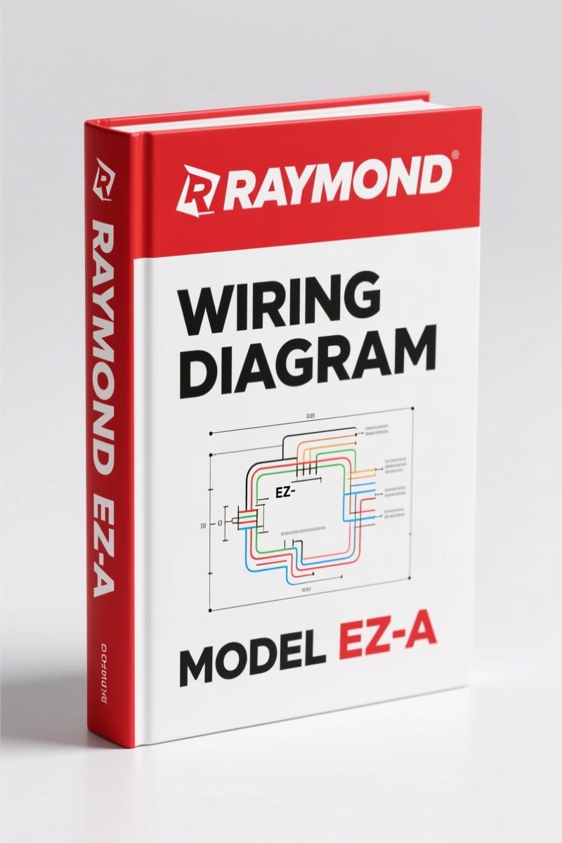
Raymond EZ-A EZ-B 2010 Wiring Diagram – 13-Page OEM Schematic
Original price was: $63.90.$45.00Current price is: $45.00.
OEM wiring diagram for Raymond EZ-A, EZ-B, ET-A, ET-B, ES-B (2010). 13 pages. Contactors, motor velocity, sensor circuits.
Description
Raymond EZ-A, EZ-B, ET-A, ET-B, ES-B 2010 Wiring Diagram – A Tech’s Take
I’m Mike Callahan, 28-year ASE Master Technician. I’ve seen more burned-up wire harnesses from guesswork than I care to count. If you’re working on a Raymond EZ-A, EZ-B, ET-A, ET-B, or ES-B reach truck from 2010, this Raymond EZ-A, EZ-B, ET-A, ET-B, ES-B 2010 Wiring Diagram is what you need on the bench—not some aftermarket photocopy that swapped pins 2 and 15. This is the real OEM publication 1122990A, issued July 1, 2010, with 13 pages of factory wiring data. Let’s walk through what you get and why it matters.
First thing I do when a truck comes in with a dead contactor or intermittent motor fault—I flip to page 1. That page has the contactor panel layout. You see TP1, TP2, TP3, TP4, TP5 test points and the three main fuses: FU1 at 150A, FU2 at 350A, FU3 at 500A. Miss one of those and you’ll be replacing a drive controller for no reason. The manual labels every terminal: STR, LPC, TPC, TA. No guessing which post gets B+.
I’ve watched guys skip the fuse check and go straight to replacing the contactor. That’s a waste of a Saturday and the customer’s money. The OEM wiring diagram gives you the exact current path so you can verify voltage drop without pulling every panel off.
Contactor Panel Layout: Fuses and Connectors
Page 1 of the Raymond 2010 schematic shows the contactor panel with FU1, FU2, FU3, and the STR, LPC, TPC contactor coils. You’ve got TP1 through TP5 test points. Connector numbering matches the physical harness: JPL1-3, JPS1-8, JPT3-2. If you’re chasing a no-power condition, probe TP5 first. If you get B+ there but nothing at TPC output, the 500A fuse is open or the contactor driver circuit is down. The manual’s schematic makes that chain obvious—no need to trace wires blind.
Motor Velocity and Temperature Sensors: Reading the Schematic
On the same page, look at the motor velocity section. For the traction motor, T VEL SENSOR+ at ID2-20, T VEL SENSOR- at IDGND-21. For the lift motor, L VEL SENSOR+ at JPL2-1, L VEL SENSOR- at JPL1-3. The manual also shows motor temperature sensors: T TEMP+ at JPT3-16, T TEMP- at JPT3-17, and L TEMP+ at JPL3-16, L TEMP- at JPL3-17. If you get a speed sensor fault code, you can probe these pins directly at the controller without back-probing harness connectors. That saves half an hour of disassembly.
Temperature sensor circuits are often overlooked. A lift motor that’s running hot but not throwing an overtemp code usually has a bad L TEMP+ connection. The schematic shows you exactly that wire goes to JPS1-9. Check continuity there before you condemn the motor.
Primary Control Handle Wiring: P-Throttle, Lift, Reach, Horn
The primary control handle section on page 1 lists every function pin: P_THROTTLE, LIFT, P_HORN, REACH, RETRACT, TILT UP, TILT DOWN, SSHIFT LEFT, SSHIFT RIGHT, DGND. Also a connector for H_HTR, HGG CNTRL PWM, HGG FAULT, HGG CONTACTOR, THERM EN. If the reach function is dead, check pin 4 on the handle connector for voltage. The manual shows that reach signal goes through JPC10-3 to the controller. I’ve seen a broken wire inside the handle boot that didn’t show on a visual—only the schematic told me which pin to backprobe.
Sounders, alarms, and auxiliary outputs are all mapped. AUX1, AUX2, DUMP, L/L are listed with their B+ and ground returns. For a lift-interrupt issue, verify L/L pin 15 at JPC20-16. That kind of detail keeps you from ordering parts you don’t need.
Does This Manual Cover the Fuel System?
No. This is an electric reach-fork truck. There’s no fuel system. The wiring diagram covers the 3-motor electrical schematic for series ES/ET/EZ-A/ES-xD/ET-xD/EZ-AD. If you need hydraulic or engine data, those are in the separate maintenance manual PDMM-0080-01.
3 Motor Electrical Schematic Overview
Figure 1 on page 2 is the full electrical schematic for the 3-motor configuration. It includes the contactor panel, motor velocity circuits, primary control handle, display bus (BUS_I+, BUS_I-, BUS_J+), steer control (CCW_PWM, CW_PWM, STEER_CURRENT, NEUTRAL_PULSE), and the sounder/alarm circuits. The schematic breaks down into subsystems but keeps the interconnects clear. You can trace a fault from the battery B+ terminal all the way to the motor phase wires without flipping pages every ten seconds.
One thing that bothers me about aftermarket wiring diagrams: they often consolidate multiple revisions into one drawing and miss the 2010 update that changed the steer feedback connector. This factory manual is the 2010 revision, dated July 1, 2010. It’s the exact version that matches the truck build date. Use anything else and you risk wiring an internal thermistor to a speed sensor pin.
Why OEM Wiring Diagrams Beat Aftermarket Prints
I’ve got a stack of aftermarket wiring diagrams in my trash can. They leave out test points, fuse ratings, and controller pin numbers. This Raymond OEM document gives you every terminal ID, every connector number (JPC14-5, JPC12-1, etc.), and every wire color. Red is pin 1, black is pin 4, white is pin 3, blue is pin 2—that’s from the motor temperature sensor wiring on page 1. Aftermarket prints will tell you “red to sensor” but not which pin. On a 150-pin controller, that makes the difference between a one-hour diagnosis and a four-hour doorstop.
If you want to confirm the authenticity, look at the footer: “Publication: 1122990A, Issued: 01 Jul 2010, ©2010 The Raymond Corporation.” That’s the real deal. No third-party reprints.
Related Manuals
- Raymond 111, 112, 113, 114, 11XD 2010 Electrical Schematic – OEM Factory Wiring
- Raymond TRT 2010 Electrical Schematic
- Raymond 111 112 113 114 2010 Electrical Schematic
For additional background on reading wiring diagrams, check out Automotive Wiring and Automotive Wiring from the Society of Automotive Engineers.
FAQ
- Q: Can I use this wiring diagram for the EF model?
- A: No. This manual covers EZ-A, EZ-B, ET-A, ET-B, ES-B only.
- Q: How do I read the motor velocity sensor section on page 1?
- A: The schematics label sensor pins by function and connector. For the traction motor: T VEL SENSOR+ is at ID2-20, T VEL SENSOR- at IDGND-21, T VEL PHASE A and PHASE B at JPL1-3 pins 5 and 6. The wires are color-coded—red for sensor+, black for sensor-, white and blue for phase outputs. To test, backprobe the controller at those terminals with the key on. If you see a square wave on the phase lines when rotating the motor, the sensor and harness are good. If you get steady DC or nothing, the sensor is dead or the harness is pinched. The manual does not supply waveform values—those are in the maintenance manual—but the pinout alone prevents miswiring.
Stop chasing electrical ghosts with vague diagrams. Access the Factory Manual add it to your toolbox.
Additional information
| Brand | Raymond |
|---|---|
| Language | English |
4 reviews for Raymond EZ-A EZ-B 2010 Wiring Diagram – 13-Page OEM Schematic
You may also like…
-
Sale!
Raymond 111, 112, 113, 114 2010 Electrical Schematic – OEM Wiring Diagram
Original price was: $15.83.$11.99Current price is: $11.99. -
Sale!
Raymond 111-114 11XD 2010 Electrical Schematic – 24-Page OEM Wiring
Original price was: $19.80.$15.00Current price is: $15.00. -
Sale!
Raymond 440C30-470C40 2010 Electrical Schematic – 35 Pages
Original price was: $23.68.$14.99Current price is: $14.99. -
Sale!
Raymond TRT 2010 Electrical Schematic – OEM Wiring Manual (15 Pages)
Original price was: $18.14.$14.99Current price is: $14.99.
Related products
-
Sale!
E-P Equipment CPCD40-RG24, CPCD45-RG24 2006 Operators Manual – OEM Specs
Original price was: $12.10.$10.00Current price is: $10.00. -
Sale!
E-P Equipment R Series 2005 Operators Manual – Forklift Ops & Maintenance
Original price was: $12.49.$9.99Current price is: $9.99. -
Sale!

Taylor T-180S, T-360L, TH-300L, TH-350L, TB-180S Service Manual – 298 Pages OEM
Original price was: $38.70.$30.00Current price is: $30.00. -
Sale!
Taylor TX180S TXH300L TXH350L TXH400L TXB180S 2007 Service Manual – Factory Specs
Original price was: $39.60.$30.00Current price is: $30.00.
James L. –
This is just what I was looking for. It is easily zoomable on my phone without blur. Contains detailed wiring diagrams for Raymond. Saved my repair job! Thank you.
pro_mechanic –
Great factory service manual. The pages are clean and easy to navigate. Contains detailed schematics for Raymond. Saves me a lot of dollars.
Robert M. –
Excellent factory service manual. It is easily zoomable on my iPad without blur. Contains precise wiring diagrams for Raymond. Saves me hundreds of money.
David K. –
Great buy! The document quality is excellent. Every wiring layout is included for Raymond EZA. I will definitely buy again.