
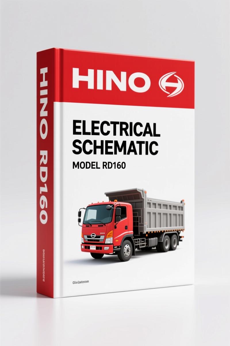
Hino RD160 Electrical Schematic – 14-Page OEM Wiring Diagram
Original price was: $20.13.$16.50Current price is: $16.50.
14-page OEM Hino RD160 electrical schematic covering brake system, starting circuit, and harness routing. Factory-accurate wiring data.
Description
Hino RD160 Electrical Schematic
I’ve been turning wrenches for 28 years, and the one thing that burns me up is chasing a ghost in a truck’s wiring because some aftermarket diagram guessed the pinout. You get a Hino RD160 in your bay with a no-crank condition, you don’t have time to play pretend. This Hino RD160 Electrical Schematic is the real factory document — the same one Hino technicians pull up when they’re flat-rate and need answers fast. It’s 14 pages, all original Japanese/English mixed labeling, straight from the OEM vault.
Brake System Intersection Diagram
The schematic kicks off with the brake air system — that’s the first page you see. It traces every check valve, air dryer, protection valve, and the 18-liter tanks front and rear. If you’re chasing a pressure drop or a solenoid (magnetic valve) that won’t trigger the idle map controller, this is where you start. The document labels each component in both Japanese and English, so there’s zero guesswork on which line is “REAR BREAK” vs “FRONT BREAK.” I’ve had guys wire an exhaust brake backwards because they trusted a third-party re-draw. Don’t be that guy.
Does This Cover the Full Electric Wiring?
Yes — the electric wiring section splits into three harnesses: Front, Inter (intermediate), and Rear. You get the power supply circuit (A), starting/charging circuit (B), and starting support circuit (C). The starter safety switches are shown in multiple positions — there’s a reason for that. Hino uses several interlock switches on the clutch and transmission to prevent cranking. This schematic shows where each switch sits in the circuit, so you can isolate a bad switch with a multimeter instead of replacing parts blind. Never trust a diagram that simplifies safety interlocks into a single generic symbol.
3 Harness Sections, 14 Pages of Factory Data
Fourteen pages might sound thin, but every page is packed. You get the junction box layout, battery link connections, starter relay positions, and alternator wiring. The document even includes a diagram for the “Unload” protection valve and the air suspension’s control solenoid — things that aftermarket schematics often skip because they’re truck-specific. If you’re working on a Hino RD160 equipped with air suspension, you need this page. I’ve seen a shop lose a whole day because they didn’t know the air suspension and brake circuits share a pressure regulator. Page 2 tells you exactly how they split.
Understand the Starting Circuit Before You Crank It
Look at the starter safety switch repeat — it appears over a dozen times in the schematic because Hino wired multiple series switches into the circuit. That’s not a mistake. Each switch (transmission neutral, clutch pedal, battery switch) has to be closed before the starter relay gets power. If you skip verifying all of them, you’ll end up replacing a perfectly good starter. The schematic also shows the battery switch and junction box orientation — critical when you’re replacing a truck’s main harness. I always photocopy this page and tape it to the battery box before disconnecting anything.
Power Supply and Starting Circuit: What the Schematic Shows
The power circuit (A) runs from the battery switch through the junction box to the main breakers. The starting charging circuit (B) ties the alternator, battery link, and starter relay together. The support circuit (C) includes the starter safety switches and the idle map solenoid. Every wire is drawn with its path — no hidden splices or ambiguous dashed lines. This is OEM documentation, not a simplified training handout. The difference is night and day when you’re diagnosing an intermittent short that only shows up under load.
Who Needs This Manual on Their Bench
If you own a Hino RD160 truck — whether it’s a dump truck, a flatbed, or a chassis cab — this schematic belongs in your shop. Same if you’re a fleet mechanic covering multiple Hino models. The wiring is unique to the RD160; don’t assume it matches the RB145 or Rainbow series. For beginners, yes, you can use this as long as you understand basic electrical theory. Start with the power supply circuit and trace each wire with a test light. Experienced techs will appreciate having the factory labeling so they can order the exact Hino part number for a bad check valve or magnetic valve. Safety-wise: never probe a circuit without confirming the battery disconnect location on the diagram. This schematic shows it.
OEM vs Aftermarket: Why This Document Wins
Aftermarket electrical schematics for the Hino RD160 are usually redrawn from memory or from a single truck that had modifications. I’ve seen aftermarket diagrams swap the front and rear tank connections — that’ll cost you a brake valve if you follow them. This copy is a direct scan of the original Hino publication. The Japanese terms are there alongside the English translations, which means a translator didn’t guess what “プロテクションバルブ” meant. It means protection valve. Period. You’re paying for accuracy, not convenience.
Frequently Asked Questions
- Does this schematic include wiring color codes?
- No. The schematics show wire paths and component connections but don’t list color codes. You’ll need a multimeter and the factory wiring harness layout for that level of detail. This is a circuit diagram, not a pinout table.
- Is the manual in English or Japanese?
- Both. The document uses Japanese labels with English translations directly next to them. For example, “ブレーキ バルブ” is followed by “BREAK VALVE.” You don’t need to read Japanese to follow it.
- Can I use this for a Hino RD160 with a different engine?
- Yes — the electrical schematic covers the chassis wiring common to the RD160 regardless of the engine variant. The power supply, starting circuit, brake system, and air suspension wiring are the same. Engine-specific wiring, like the J08E-TI sensor harness, is not included. Check our Hino J08E-TI Workshop Manual for that.
- How do I know the wiring matches my year of production?
- The Hino RD160 was produced over several years with minor electrical changes. This schematic appears to be a mid-cycle version. If your truck has a different battery switch layout or an added ABS module, you’ll need to cross-reference with a later revision. For most standard RD160s, it’s accurate. Call us if you have the VIN and we can verify the original file name Hino_RD160_Electrical_Schematic_en-ja-30724010351.pdf matches your configuration.
Related Manuals
- Hino Model RB145 Electric Wiring Diagram
- Hino Rainbow P-RH 160 Instruction Manual
- Hino J08E-TI Workshop Manual
For background on how to read truck wiring diagrams, see Automotive Wiring basics. For an overview of the Hino product line, check Automotive Industry Overview.
If you’re tracing a short on a Hino RD160 or replacing a wiring harness, stop working from memory. Fourteen pages won’t waste your time — they’ll save it. Access the Factory Manual and get the circuit straight the first time.
Additional information
| Brand | Hino |
|---|---|
| Language | English |
2 reviews for Hino RD160 Electrical Schematic – 14-Page OEM Wiring Diagram
You may also like…
-
Sale!
Hino FC6J, FC9J, FD8J, GD8J, FG8J Workshop Manual – 382 Pages
Original price was: $61.65.$45.00Current price is: $45.00. -
Sale!
Hino FD, FE, FF, SG 2002 Workshop Manual – 374 Pages OEM
Original price was: $54.45.$45.00Current price is: $45.00. -
Sale!
Hino RB 14 Workshop Manual – 266-Page OEM Service Document
Original price was: $70.20.$45.00Current price is: $45.00. -
Sale!
Hino FR1E, FS1E, FY1E, SH1E, SS1E Workshop Manual – 596 Pages
Original price was: $68.40.$45.00Current price is: $45.00.
Related products
-
Sale!

2005 Parts Catalog – International NGD 3.0 L Engine (77 pages)
Original price was: $44.70.$30.00Current price is: $30.00. -
Sale!

1993 Operators Manual – International Bus 1000-3000 OEM Specs
Original price was: $12.30.$7.99Current price is: $7.99. -
Sale!
1994 Troubleshooting Manual – International 1000-4000 FBC
Original price was: $60.00.$50.00Current price is: $50.00. -
Sale!

2011 Parts Catalog – International Truck OE Parts Documentation (1786 Pages)
Original price was: $34.50.$25.00Current price is: $25.00.
Thomas B. –
Perfect OEM spec sheet. Instant access after checkout process. Contains detailed schematics for Hino. Saves me a lot of money.
John S. –
Excellent workshop guide. The text is searchable and well indexed. Every torque spec is included for Hino RD160. Highly recommended for mechanics.