
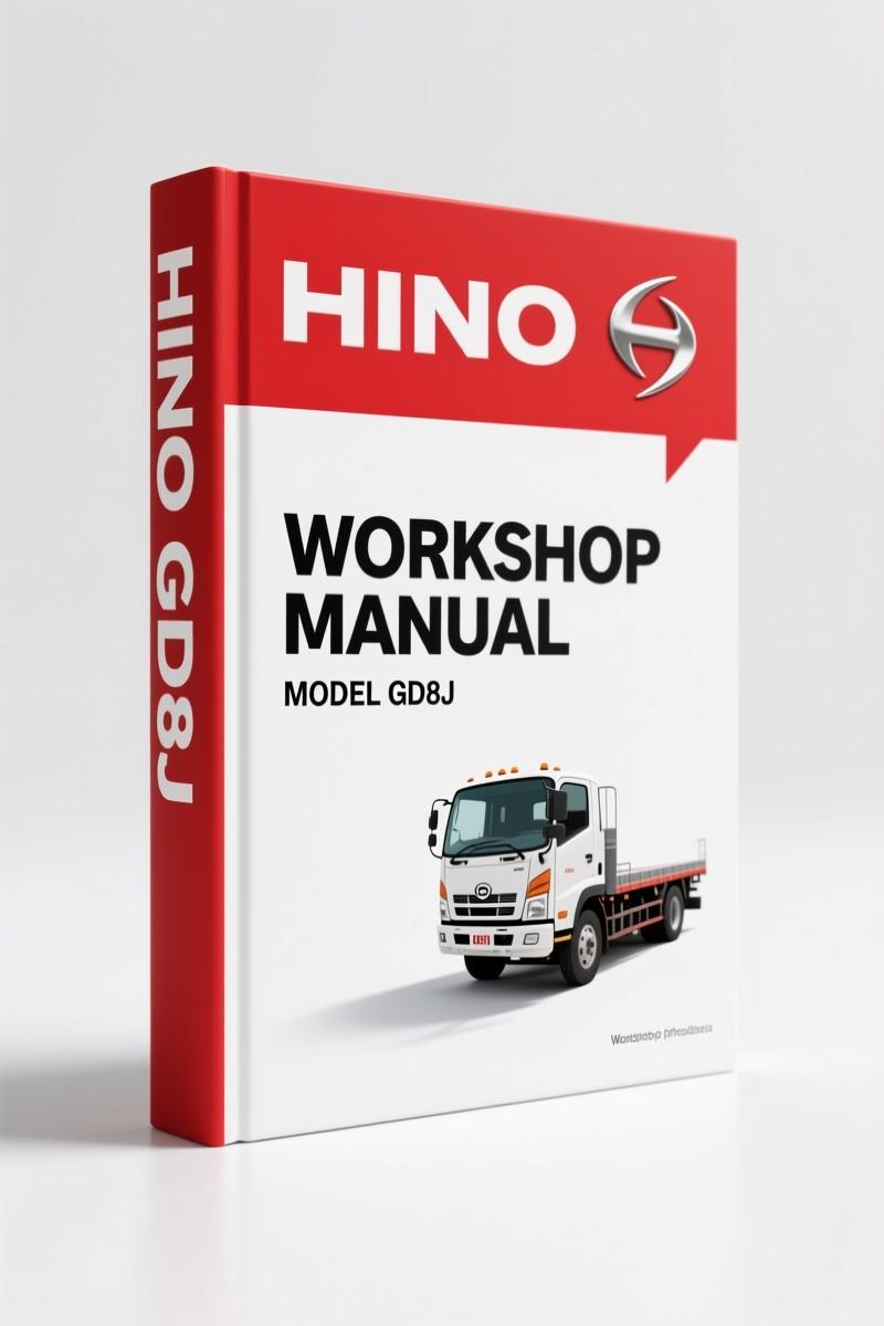
Hino FC6J, FC9J, FD8J, GD8J, FG8J Workshop Manual – 382 Pages
Original price was: $61.65.$45.00Current price is: $45.00.
OEM electrical workshop manual for Hino FC6J–FG8J series. Wiring diagrams, connector locations, fuse and relay block data – 382 pages.
Description
Hino FC6J, FC9J, FD8J, GD8J, FG8J Workshop Manual – The Only OEM Electrical Source You Need
I’ve seen too many guys chase electrical ghosts with aftermarket wiring diagrams that are wrong. Connector pinouts that don’t match, relay locations that are reversed, fuse block layouts that leave you scratching your head. That stops when you crack open the Hino FC6J, FC9J, FD8J, GD8J, FG8J Workshop Manual. This is the same binder the dealer techs used – 382 pages of factory wire routing, connector indexes, and relay positions. Not a reprint, not a photocopy. Direct from Hino Motors. You don’t guess with electrical systems. You trace.
Page 1 of the foreword states that this manual covers FC6J, FC9J, FD8J, GD8J, FG8J series along with GH8J, FL8J, FM8J, FM1A, FM2P, FT8J, GT8J, SG8J. It’s the electrical circuit volume for the J05D-TI, J05E-TI, J08E-TI, A09C, and P11C engines. If you work on any of those powerplants, this wiring book is your baseline. The index on page 2 lists the chassis group breakdown. Page 3 kicks off the actual ELECTRIC WIRE chapter, starting with a diagram section that includes a full HOW TO USE THIS CHAPTER guide. That alone saves you from misreading a wire color code.
382 Pages of Factory Data – No Aftermarket Shortcuts
Aftermarket manuals love to skip the detail. This one doesn’t. You get the WIRING DIAGRAM spanning from EL02-14 through EL02-190, every connector drawn with terminal numbers, harness side codes, and part numbers. Then the WIRE TO WIRE CONNECTOR section (EL02-190 to EL02-209) and JUNCTION CONNECTOR (EL02-209 to EL02-216). If you’re trying to figure out where a wire terminates or which cavity carries the ABS signal, it’s in here. The CONNECTOR LOCATION diagrams run from EL02-216 to EL02-336 – that’s 120 pages of physical placement. Relay locations, fuse and relay blocks, fusible link blocks, and the wire-to-wire box are all mapped. There’s even a CONNECTOR INDEX starting at EL02-351 so you can cross-reference part numbers. You don’t flip through guessing.
Electric Wire Section: How It’s Organized
Open the manual and you see a clean structure. FOREWORD, INDEX, then the ELECTRIC WIRE chapter. Inside that chapter, the DIAGRAM subsection includes HOW TO USE THIS CHAPTER, CONTENTS AND QUICK REFERENCE, WIRING DIAGRAM, WIRE TO WIRE CONNECTOR, JUNCTION CONNECTOR, CONNECTOR LOCATION, RELAY LOCATION, FUSE AND RELAY BLOCK, FUSIBLE LINK BLOCK, WIRE TO WIRE BOX, and CONNECTOR INDEX. Each subsection is labeled with an EL02-xxx page number. Need the fusible link block layout? Flip to EL02-348. Want to see where relay R1 sits? Look at RELAY LOCATION starting EL02-336. The book is designed for a tech on a time clock. Grab it, find the section, get the spec, close it.
For the engine-specific wiring – like the J08E-TI or J05E-TI – you’ll want to pair this electrical volume with the corresponding engine manual. The Hino J08E-TI Workshop Manual – OEM Factory Specs for Diesel Engine gives you the sensor pinouts and actuator tests that supplement the chassis wiring. Same for the Hino J05D-TI, J05E-TI Workshop Manual – 454-Page OEM Factory Book. And if you’re dealing with the J08C-TI, the Hino J08C-TI Workshop Manual – Factory Specs & Torque Data has the mechanical specs you’ll need alongside the electrical diagrams.
What Does the ‘HOW TO USE THIS CHAPTER’ Section Cover?
Page 4 shows you exactly how to read the wiring diagram symbols – the connector codes, terminal numbers, harness side indicators, and circuit serial numbers. There’s a sample diagram with annotations explaining each element: the male connector code, part number, wire colors, and cross-reference to the connector index. That page alone prevents the classic mistake of probing the wrong cavity. The manual also explains the junction connector symbols and how wire-to-wire boxes are labeled. After you study that page, you’ll decode the entire 176-page wiring diagram correctly.
Need background on how manual transmissions interact with the electrical system? The Manual Transmission overview covers clutch switches and reverse light circuits that tie into the chassis wiring. Similarly, the Manual Transmission resource explains the shift lever position sensor wiring – useful when diagnosing starting circuit issues on these Hino trucks.
Get the Right Torque Specs from the Workshop Manual
This is an electrical manual, so torque data is limited to connector bolts and ground studs. But the real value is in the OEM wiring diagrams – every splice, every fuse rating, every relay pin. The CONTENTS AND QUICK REFERENCE (EL02-7) lists each circuit group by system: ABS, engine control, transmission, lighting, etc. You find the system, trace the wire number, check the connector location, and verify the circuit. No more flipping between five different aftermarket PDFs with incompatible numbering. One source. Factory approved.
Short paragraph: A few guys think they can skip the connector index. Don’t.
That index (EL02-351) cross-references every connector part number to its location diagram. Without it, you’re wasting time pulling panels to find a connector that’s two feet from where you think it is. Use the index.
Source Validity – Why OEM Beats Aftermarket Every Time
Hino Motors printed this manual. The foreword states: “All information and specifications in this manual are based upon the latest product information available at the time of printing.” There’s a publication number (S1-YFCE18K 1/3) and copyright protection. No third-party interpretations. The diagrams show actual wire colors, actual connector shapes, actual fuse block layouts. An aftermarket manual will simplify a 12-wire connector down to a generic 8-pin drawing. This one gives you the full terminal arrangement. If you’ve ever been burned by a mislabeled aftermarket ABS circuit, you’ll appreciate the difference.
Stop chasing bad wiring and Access the Factory Manual now. It’s the only way to guarantee you’re working from Hino’s original data, not a reprint that introduced errors.
- Is this the complete workshop manual for the truck?
- No, this volume covers the electrical wire section only. It includes all wiring diagrams, connector locations, and relay positions for the FC6J, FC9J, FD8J, GD8J, FG8J series.
- What engine models are covered in the wiring diagrams?
- The foreword lists J05D-TI, J05E-TI, J08E-TI, A09C, and P11C engines. Each engine’s electronic control system wiring is represented in the WIRING DIAGRAM section – from the ECM power supply to the fuel injection solenoid circuits. The diagrams show specific connector pin assignments for the engine harness, including the CAN bus lines, injector drive circuits, and sensor grounds. You’ll also find the ABS control unit, transmission shift solenoids, and body electrical circuits. For mechanical engine overhaul, refer to the separate engine workshop manual listed in the foreword.
Additional information
| Brand | Hino |
|---|---|
| Language | English |
2 reviews for Hino FC6J, FC9J, FD8J, GD8J, FG8J Workshop Manual – 382 Pages
You may also like…
-
Sale!
Hino RB 14 Workshop Manual – 266-Page OEM Service Document
Original price was: $70.20.$45.00Current price is: $45.00. -
Sale!

Hino FR1E, FS1E, FY1E, SH1E, SS1E Workshop Manual – 596 Pages
Original price was: $68.40.$45.00Current price is: $45.00. -
Sale!
Hino FD, FE, FF, SG 2002 Workshop Manual – 374 Pages OEM
Original price was: $54.45.$45.00Current price is: $45.00. -
Sale!
Hino E13C Workshop Manual – 412 Pages | AutoFix Global
Original price was: $64.80.$45.00Current price is: $45.00.
Related products
-
Sale!

1991 Operators Manual – International Truck OEM Specs (108 Pages)
Original price was: $13.63.$10.99Current price is: $10.99. -
Sale!

Acura NSX 1991 Service Manual – 1420 Pages OEM
Original price was: $102.05.$65.00Current price is: $65.00. -
Sale!

Technical Manual – International DT 530 & HT 530 (118 Pages)
Original price was: $37.00.$25.00Current price is: $25.00. -
Sale!

1995 Operators Manual – International 1000-4000 Series | OEM Documentation
Original price was: $12.49.$9.99Current price is: $9.99.
David K. –
Great OEM spec sheet. The text is searchable and well indexed. It guided me to rebuild my Hino FC6J, engine. Highly recommended for mechanics.
gearhead88 –
I am very pleased with this transaction. The pages are clean and well indexed. A must-have for any Hino FC6J, owner doing maintenance. Great value for money.