
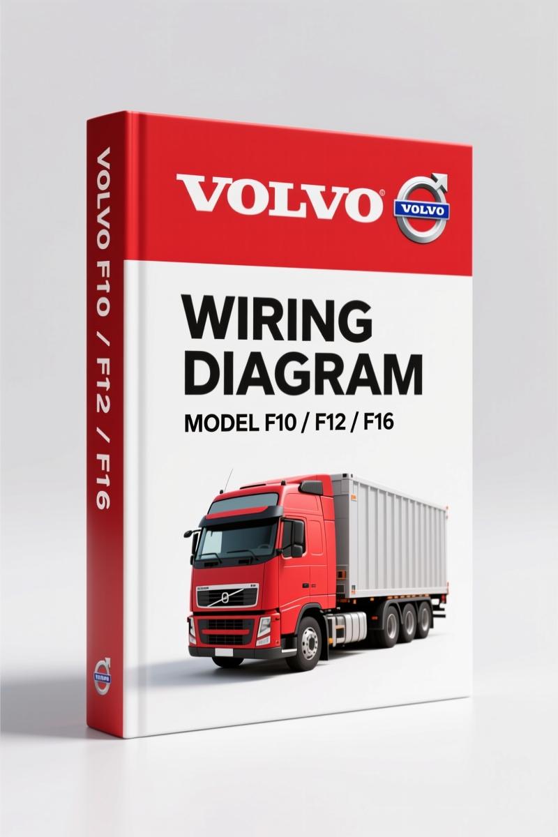
Volvo Penta F10, F12, F16 Wiring Diagram – 142 Pages Factory Electrical Schematics
Original price was: $42.30.$30.00Current price is: $30.00.
Factory wiring diagram for Volvo Penta F10, F12, F16 trucks. 142 pages of component wiring, fuses, connectors, and harnesses. Official OEM documentation.
Description
Volvo Penta F10, F12, F16 Wiring Diagram – Factory OEM Manual
You’ve been handed a truck with a dead short, or maybe the fuel injection won’t fire, and the aftermarket diagram you pulled off the web has the wire colors swapped and the pinouts guessed. That’s when you lose a day chasing ghosts. This Volvo Penta F10, F12, F16 Wiring Diagram is the actual factory PDF that Volvo Truck Corporation printed under order number TSP 23688/1. It’s 142 pages of nothing but OEM wiring – no generic sketches, no “universal” nonsense. Every component, every connector, every circuit as Volvo built it. I’ve used these diagrams to track down a bad splice on a GEARTRONIC LO circuit (page 26-27) in under an hour. You don’t guess with electrical – you follow the factory path or you buy new ECUs.
Why Factory OEM Wiring Diagrams Matter
A wiring diagram from a third-party publisher is a gamble. They copy and redraw, and somewhere in that process a resistor value changes or a ground point gets dropped. The result? You connect a wire that should read 24 V and instead you get smoke. This manual is a direct scan of the Volvo original – same page numbers, same letter codes (AA for starter motor, BN for fuel injection, OA for ABS). When the manual says connector XA (page 44) has six fuses, you can bet your meter that’s exactly what you’ll find. Aftermarket diagrams don’t carry that kind of guarantee. I’ve seen guys swap an alternator three times because a generic diagram showed the B+ terminal on the wrong side. Don’t be that guy.
What This 142-Page Manual Covers
This is not a repair manual – it’s a pure wiring diagram index. The table of contents lists component wiring diagrams from page 5 through page 47. That includes the big-ticket items: starter motor and alternator (AA, 24 V system), electrically controlled fuel injection (BN), speed limiter (BK), engine-switch-off (BG), and the entire lighting suite – from dim-dip (CE) to rotating warning lights (ER). But it goes deeper. You’ll find the climat unit (HA) with AC and ATC variants, parking heater DW80 (HC), central lock (LC), power take-off (LD and LE), diff lock (LG), bogie lift with air suspension (MA through MX), and the full driver information system (NK). The GEARTRONIC LO shift-by-wire system is on pages 26-27 – a critical section if you’re chasing a no-start that isn’t fuel or crank. Also covered: ABS anti-lock brakes (OA, OB) with 6-channel variant, electromagnetic brake (OD), and hydrodynamic brake (OG). All wire colors, all connector pin numbers, all fuse locations. If you’re working on an F10, F12, or F16 LHD configuration, this is your roadmap.
Pages 126-127 show cable harness routing, page 130 has the circuit card for the electrical centre, and pages 130-133 list every fuse and connector by ID. The component list on pages 132 and 134-135 is a quick reference when you need a part number for a relay. I keep a printed copy of that list taped to my toolbox.
Audience Fit – Who Needs This?
If you own a Volvo F10, F12, or F16 truck – or you’re a shop that services them – this manual is not optional. The aftermarket wiring diagrams you find on free sites are wrong enough to cost you hours. Home garage enthusiasts who work on their own rig will save themselves the headache of a fried ECU by using factory-specified wire gauge and fuse ratings. Professional techs who bill by the hour need the accuracy to trace a fault through the bogie lift circuit (MK or MP) without false leads. And if you’re restoring an older Volvo Penta marine engine that shares these truck-based electrical systems, the fuel injection wiring (BN) and starter-alternator (AA) data apply directly. I’ve used the same diagram to troubleshoot a F12 in a yard truck and a F16 in a highway hauler. The wiring doesn’t lie – the aftermarket diagrams do.
Source Validity – Why Aftermarket Diagrams Fail
Let me put this plainly: I have torqued more head bolts than most people have had hot meals, and I have replaced more wiring harnesses because of bad aftermarket diagrams than because of actual failures. The factory manual you get here is a direct reproduction of Volvo’s own TSP 23688/1 bulletin set. It replaces service bulletins T-37-0-69, 37-0-72, 37-0-77, and 37-0-83 – meaning this is the corrected, updated version. No third-party publisher has touched it. If you see a wire labeled BK (speed limiter) you know it’s Volvo’s code, not some translator’s guess. Aftermarket manuals often merge circuits across model years, which is how you end up with a 24 V starter signal going through a 12 V relay. This manual is model-specific: F10, F12, F16 LHD. That’s it. For related factory diagrams, check the Volvo Penta FE 2009 Wiring Diagram – Factory OEM Manual for newer chassis, the Volvo Penta EC140B Wiring Diagram – 19-Page Factory Manual for compact excavator wiring, or the Volvo Penta 440, 460, 480 1991 Wiring Diagram – Factory OEM Manual for older marine applications. For a deeper understanding of how to read electrical schematics, Automotive Wiring basics on Wikipedia are a decent start, but nothing replaces this printed factory original. And when you’re deep in the harness, Automotive Wiring standards help, but the manual’s color codes are the only ones you should trust.
- Does this manual include torque specs for engine components?
- No. This is a wiring diagram only. It does not contain engine mechanical data, torque values, or repair procedures.
- I have a F10 with a non-running fuel injection system – which page do I turn to first?
- Page 8. That’s the BN section for electrically controlled fuel injection. The diagram shows the ECU, injector solenoids, and all sensor inputs. Trace power at pin 1 (ignition +24 V) then ground at pin 2. If you have voltage but no injector pulse, check the speed limiter (BK, page 7) – it can cut fuel if the vehicle speed sensor fails. After that, inspect the engine-switch-off circuit (BG, page 6) – a short-to-ground there will kill the injection relay. I’ve fixed two F16s where a chafed wire in the BG harness was the only fault. The manual shows exactly where those wires run through the cab harness.
You don’t need to gamble with a wiring fault. The factory diagram is the difference between a 20-minute fix and a two-day strip-down. Access the Factory Manual now and get the circuit paths that Volvo designed. Your multimeter will thank you.
Additional information
| Brand | Volvo Penta |
|---|---|
| Language | English |
4 reviews for Volvo Penta F10, F12, F16 Wiring Diagram – 142 Pages Factory Electrical Schematics
You may also like…
-
Sale!
Volvo Penta TD520GE, TAD520GE, TD520VE, TD420VE, TAD420VE 2007 Workshop Manual
Original price was: $64.00.$50.00Current price is: $50.00. -
Sale!
Volvo Penta B7, B9, B12 2007 Wiring Diagram – Factory Electrical Schematics
Original price was: $71.10.$45.00Current price is: $45.00. -
Sale!
Volvo Penta FH, FM Technical Manual – Factory Specifications for Suspension & Emissions
Original price was: $79.00.$50.00Current price is: $50.00. -
Sale!
Volvo Penta D12A, D6B, D12C Technical Manual – 23-Page Factory Abbreviation Reference
Original price was: $67.50.$50.00Current price is: $50.00.
Related products
-
Sale!

1992 Electrical Schematic – International 1000/3000/4000/2554 OEM Wiring Diagrams (132 Pages)
Original price was: $26.40.$20.00Current price is: $20.00. -
Sale!

1989 Service Manual – International 2000-8000 Electrical Systems
Original price was: $72.00.$50.00Current price is: $50.00. -
Sale!
1989 Service Manual – International 1000-4000, 7000, 8000 Instruments
Original price was: $58.80.$40.00Current price is: $40.00. -
Sale!

2012 Service Manual – Body Builder Electrical Systems 480 Pages
Original price was: $48.28.$34.00Current price is: $34.00.
John S. –
This is just what I needed. It is easily zoomable on my laptop without blur. Every wiring layout is provided for Volvo Penta Penta. Highly recommended for mechanics.
James L. –
This is just what I was looking for. The file quality is excellent. Contains precise wiring diagrams for Volvo Penta. I will recommend this shop to others.
diy_master –
Five stars! Immediate link after checkout. Contains clear schematics for Volvo Penta. Saves me hundreds of money.
Richard G. –
I am so happy with this manual. Instant access after checkout. It assisted me to repair my Volvo Penta Penta transmission. I will recommend this shop to others.