
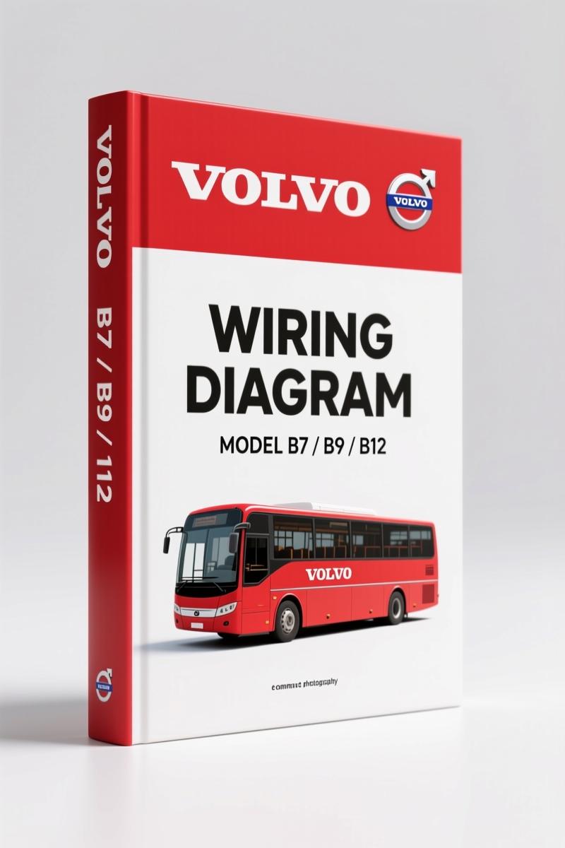
Volvo Penta B7, B9, B12 2007 Wiring Diagram – Factory Electrical Schematics
Original price was: $71.10.$45.00Current price is: $45.00.
Factory-authored 2007 wiring diagram for Volvo Penta B7, B9, B12. 143 pages covering ignition, EECU, fuel systems, and more.
Description
Volvo Penta B7, B9, B12 2007 Wiring Diagram
If you’re chasing a short in a Volvo Penta B7, B9, B12 2007 Wiring Diagram, you need the factory document – not a re-drawn copy from some third party. I’ve been wrenching 28 years, and I’ve seen too many guys blow ECUs because they guessed the pinout from an aftermarket schematic. This is the real deal: 143 pages of OEM wiring that Volvo Bus Corporation released in 2007, document number 20904123, index 04. It covers everything from the ignition system (page 02) to the ground page (page 59) and every CAN bus variant in between. The copying, distribution and utilization of this document without authorization is prohibited – that tells you how seriously Volvo treats this information. You should too.
Ignition and Starting System (AA02) – Where Your Diagnostics Start
Every electrical fault hunt begins at the ignition switch. This diagram maps the entire start/stop circuit, including rear switches (AG08), starter and alternator for MD7 (AD05), and the separate paths for R9L, R9TL, B9R (AE06). The starter relay K13 is shown with its exact pin numbers – 30, 85, 87, 87A – and the wire gauges (0.75BL/SB for example). Without this page, you’re guessing which wire feeds what. Page 02 gives you the complete ignition and starting system schematic. Use it to verify voltage drop at the starter solenoid before you replace parts.
Volvo Penta B7, B9, B12 2007 Wiring Diagram: EECU Engine Control Sections
Engine control modules are the most expensive component to fry. The manual dedicates pages 14-20 to the EECU variants: D9B (CA14), G9A (CB15), D12D (CC16), DH12E (CM19), and D7E (CN20). Each page shows the exact connector pinouts, wire colors, and CAN connections. The D9B engine page, for instance, includes the throttle position sensor feedback and fuel injection control. You get the complete wiring for the engine harness, not a generic block diagram. If you need to check fuel tank monitor, page 17 (CG) walks you through the FTM circuit. The urea dosing system (UDS) appears on pages 23-24 (CU, CV). That’s how you avoid dumping DEF into the wrong line.
Fuel System Wiring: FTM and UDS
Fuel delivery and emissions systems are where aftermarket manuals fall apart. This factory schematic shows the Fuel Tank Monitor (CG17) and the Urea Dosing System (CU23, CV24) with the exact CAN message IDs and relay controls. The wire colors are specified – 0.5GN/R for the DRC input, 0.5Y for the BBM connection. You need to see the actual splices and ground points to diagnose a fuel gauge drop-out. Page 17 includes the BIO module and articulation connections. Don’t skip it.
Does This Manual Cover the CAN Networks?
Yes. Three CAN bus pages are included: SAE J1939 (page 56), SAE J1587 (page 57), and SAE J1587 UDS (page 58). For fleet management systems, pages 53-55 (NC, ND, NE) show the FMS 200 and FMS Gateway wiring. The tachograph (NB52) and Dynafleet (NC53) are also mapped. If your bus has a Body Builder Module (BBM), pages 11-12 (BB, BC) give you the exact pins for articulation control (A90 A1, A2, A29). The A90 BBM connector pinout on page 2 of the actual diagram lists all wire colors and destinations. This is not a generic CAN layout – it’s vehicle-specific.
Source Validity – Why OEM Beats Aftermarket Every Time
Aftermarket wiring diagram publishers redraw schematics and introduce errors. I’ve personally found swapped pin numbers and missing ground points in third-party copies. This manual is a direct scan of the Volvo Bus Corporation product schematic, released under document number 20904123. The modification count and engineering release notices (ERN D-13555-75) are printed on page 1. The page numbers match the original binder: 59 pages of wiring diagrams plus 84 pages of bill of materials/component list. If you need diagrams for other marine or industrial engines, check the Volvo Penta FE 2009 Wiring Diagram – Factory OEM Manual or the Volvo Penta EC140B Wiring Diagram – 19-Page Factory Manual. For older models, the Volvo Penta 440, 460, 480 1991 Wiring Diagram – Factory OEM Manual is also available. When you need general theory on Automotive Wiring, this manual is the final authority. Don’t trust a generic Automotive Wiring guide for your Volvo Penta.
FAQ – Two Questions From Experienced Wrenches
- How do I know if this wiring diagram includes the engine control module for my specific variant?
- Check pages 14-20 for EECU coverage. Each engine variant (D9B, G9A, D12D, DH12E, D7E) has its own page. If your engine is not listed, email us the engine serial number.
- Can I use this manual to troubleshoot a start/stop system fault?
- Yes. The start/stop switches rear circuit is on page 08. But you need to trace the entire path from the ignition switch (page 02) through the starter and alternator diagrams (pages 04-09) to the VECU (page 10) and BBM (page 11). Without the full wiring path, you’ll miss a broken wire at the body builder module. I’ve seen that mistake cost a shop a full day of labor. The diagram also includes relay K13 and articulation connector A90 – you must understand those to isolate the fault. This manual gives you every connector pinout and wire color. Don’t skip the ground page (59) – bad grounds mimic switch failures.
Every time I see a technician reach for a printed-aftermarket wiring book, I cringe. This factory Volvo Penta manual costs less than one hour of diagnostic time at a dealer. Access the Factory Manual and keep it on your shop tablet. You’ll thank yourself when the next B12 rolls in with a dead CAN bus and the owner is standing over your shoulder.
Additional information
| Brand | Volvo Penta |
|---|---|
| Language | English |
2 reviews for Volvo Penta B7, B9, B12 2007 Wiring Diagram – Factory Electrical Schematics
You may also like…
-
Sale!
Volvo Penta FH, FM, NH12 Wiring Diagram – 256 Pages Factory Electrical Schematics
Original price was: $64.35.$45.00Current price is: $45.00. -
Sale!

Volvo Penta TD520GE, TAD520GE, TD520VE, TD420VE, TAD420VE 2007 Workshop Manual
Original price was: $64.00.$50.00Current price is: $50.00. -
Sale!
Volvo Penta D12A, D6B, D12C Technical Manual – 23-Page Factory Abbreviation Reference
Original price was: $67.50.$50.00Current price is: $50.00. -
Sale!
Volvo Penta FH, FM Technical Manual – Factory Specifications for Suspension & Emissions
Original price was: $79.00.$50.00Current price is: $50.00.
Related products
-
Sale!

International 1000-3000 Series Operators Manual – 132 Pages of OEM Specs
Original price was: $14.40.$10.99Current price is: $10.99. -
Sale!
1993 Electrical Schematic – International 1000/3000/4000 Bus Chassis OEM Wiring Diagrams
Original price was: $29.26.$22.00Current price is: $22.00. -
Sale!
1992 Electrical Schematic – International 1000/3000/4000/2554 OEM Wiring Diagrams (132 Pages)
Original price was: $26.40.$20.00Current price is: $20.00. -
Sale!
1991 Electrical Schematic – 112-Page OEM Wiring Diagram for International 1000-3000 Series
Original price was: $22.75.$17.50Current price is: $17.50.
Charles W. –
This is exactly what I was looking for. It is easily zoomable on my phone without blur. A must-have for any Volvo Penta Penta mechanic doing maintenance. Great value for money.
Richard G. –
Perfect workshop guide. Instant access after checkout process. Every spec sheet is included for Volvo Penta Penta. Highly recommended for mechanics.