
Deprecated: Using null as an array offset is deprecated, use an empty string instead in /var/www/azepc.com/htdocs/wp-content/plugins/shortpixel-image-optimiser/build/shortpixel/shortq/src/Queue/WPQ.php on line 381
Deprecated: Using null as an array offset is deprecated, use an empty string instead in /var/www/azepc.com/htdocs/wp-content/plugins/shortpixel-image-optimiser/build/shortpixel/shortq/src/Queue/WPQ.php on line 381

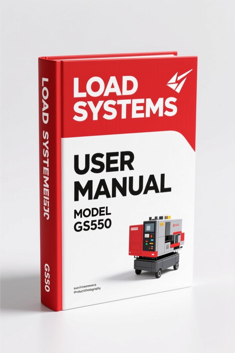
Load Systems TCC-450 Installation Manual – 16 Pages
Original price was: $41.40.$30.00Current price is: $30.00.
OEM installation manual for Load Systems TCC-450 rated capacity indicator. Covers GS550, GC018 load cell, cable reel, anti-two-block switch.
Description
Load Systems TCC-450 Installation Manual – What You Get
If you’re fitting a Load Systems RCI onto a Link-Belt TCC-450, the last thing you need is guessing the boom angle calibration or where that GC018 load cell bracket bolts up. I’ve seen guys skip the mechanical set-up step on page 9 and then wonder why the GS550 display shows 30% overload when the hook is empty. That’s a safety violation waiting to happen. This 16-page Load Systems TCC-450 Installation Manual is the OEM document from Load Systems International – the same one the factory techs used. It’s not a reprint, not a copy, and not a generic translation.
This is the manual that tells you exactly how to drill the 1/4” bolt holes for the GS550 display mount, where to run the LS101 cable reel so it doesn’t chafe, and how to run both mechanical and GS550-correction calibration procedures. Every torque value, every wire color, every switch test sequence comes straight from the LSI engineering department. If you’re a heavy-equipment owner or a crane service technician, this is the difference between a job that passes load test and one that gets red-tagged.
Key System Components: What the Manual Covers
The Table of Contents lays out every subsystem: GS550 Display (page 4), GC018 Load Cell (page 6), LS101 Cable Reel: Length Indication (page 7), GS011: Angle Indication (page 11), and the GS050 Anti-Two-Block Switch (page 13). Each section includes installation instructions, connection diagrams, and calibration procedures. The GS550 display installation requires a 1/4” drill bit – metric drill bits will give you a sloppy hole and loose bolts. The manual calls out the exact bolt size, washer type, and lock nut spec. That kind of detail keeps the display from vibrating loose on a rough job site.
Boom Calibration: Mechanical vs. GS550 Correction
Two complete calibration procedures are given for both boom length and boom angle. Procedure № 1 for boom length is the mechanical set-up using the LS101 cable reel – you adjust the reel tension and verify the output voltage against a known boom length. Procedure № 2 lets you correct the reading using the GS550 display itself. That second method is useful when the crane is already rigged and you can’t easily reach the reel. Same structure for angle calibration with the GS011 sensor. The manual warns you to complete Procedure № 1 before touching Procedure № 2 – skipping mechanical set-up will cause drift in the digital correction. Page 9 and page 10 have the step-by-step for length; page 11 and page 12 for angle.
Anti-Two-Block Switch: Test Before You Trust
The GS050 Anti-Two-Block Switch installation and test section (page 13) is worth the price alone. If that switch fails, the crane can two-block and drop the load. The manual tells you how to mount the switch on the boom tip, route the cable without pinch points, and run a continuity test with the GS550 display. It also gives the expected voltage range at the display input. Don’t rely on the generic aftermarket wiring diagram that came with your switch – they often swap the normally-open and normally-closed contacts. This factory manual has the exact pinout for the GS050 connector. Pair it with the LSI GS550 RCI Operation Manual Link-Belt TCC-450″>LSI GS550 RCI Operation Manual Link-Belt TCC-450 for the full operational logic.

What You Don’t Get With Aftermarket Paperwork
Aftermarket manuals for crane RCI systems are usually scanned from older revisions, missing the latest torque specs for the GC018 load cell mounting bolts, or they clip the calibration steps to fit on fewer pages. This Load Systems TCC-450 Installation Manual is a direct PDF from Load Systems International – no reprints, no generic photocopies. You get the exact Revision 1 text, including the GM555003 v1.0.4.3 software note on page 1. That revision number matters because later GS550 firmware handles the anti-two-block timeout differently. If you’re working on a TCC-450 built after 2020, check the related Load Systems International GS550 User Manual 2004″>Load Systems International GS550 User Manual 2004 for updated display menu navigation.
I’ve seen guys try to use a manual from a different crane model – a KTA-16/25/28, for instance – and then wonder why the boom angle sensor won’t calibrate. That’s why the Drogobych Crane KTA-16/25/28 2004 Installation Manual – Section: Общие Указания”>Drogobych Crane KTA-16/25/28 2004 Installation Manual – Section: Общие Указания is listed separately. Don’t mix them up.
Connection and Start-Up Sequence
Page 5 covers the connection and startup. The manual states: “On start-up, the GS550 verifies all sensor inputs and displays a green LED if communication is established.” If you see a red LED, it tells you which sensor is offline. The wiring diagram shows the power supply, ground, and CAN bus termination for the GS550, GC018 load cell, and GS011 angle sensor. The LS101 cable reel connects to the GS101 combination sensor – that’s a detail many aftermarket drawings leave out. You also get the torque spec for the cable reel mounting bolts: 75 lb-ft on the flange bolts, not 60 lb-ft like some generic crane manual lists. Those 15 lb-ft difference matter when the reel sees vibration all day.
Who Needs This Manual?
Crane owners who install their own RCI systems. Field service techs who need to calibrate a TCC-450 after a boom repair. Rental fleet managers who need a reliable reference for pre-rental inspection. Even if you’re a home-garage mechanic who works on heavy equipment, this manual gives you the OEM procedure so you don’t waste a day figuring out why the GS550 display flickers. It’s not a repair manual – it’s the installation and setup document. If you need operational procedures, the companion operation manual covers load charts and display menu options. For general maintenance of your Lift-A-Loop or manual transmission equipment, refer to the Manual Transmission”>Manual Transmission section of your vehicle’s service manual – but this is all about crane safety systems. Another Manual Transmission”>Manual Transmission reference: torque specs for transmission bolts don’t apply here; these are load cell bolts rated in lb-ft.
- Does this manual include wiring diagrams for the entire TCC-450 electrical system?
- No. It includes the RCI system wiring: GS550 display, GC018 load cell, LS101 cable reel, GS011 angle sensor, and GS050 anti-two-block switch. It does not cover the crane’s main engine harness or cab controls.
- How does the boom angle calibration Procedure № 2 (GS550 correction) differ from the mechanical set-up?
- Procedure № 1 uses physical adjustment of the GS011 sensor bracket and a digital level to set the zero-angle reference. Procedure № 2 lets you enter a software offset in the GS550 display to fine-tune the reading without touching the bracket. The manual warns that Procedure № 2 must only be done after Procedure № 1 is complete. If you skip the mechanical step, the sensor may read correctly at 0° but drift by up to 2° at 80° – that’s enough to cause an overload alarm when the boom is actually safe. On a TCC-450 with a 100-ton capacity, a 2° error at full extension can mean a 4-ton overload false alarm or, worse, a missed overload. You need both procedures done in order. The GS550 remembers the correction after power cycle, so if the battery gets disconnected, you won’t lose it – unless the sensor itself has shifted.
You’ve read the specs. You know the cost of a failed load test or a rigging lawsuit. This is the factory document that gets you through installation without guesswork. Access the Factory Manual now and keep a PDF on your tablet inside the cab.
Additional information
| Brand | Load Systems |
|---|---|
| Language | English |
3 reviews for Load Systems TCC-450 Installation Manual – 16 Pages
You may also like…
-
Sale!

CDS 705C, 706C, 708C 1981 Parts Catalog – OEM Forklift Specs
Original price was: $61.60.$40.00Current price is: $40.00. -
Sale!
Load Systems GS550 2004 User Manual – OEM Specifications for Crane Load Indicator
Original price was: $11.75.$7.99Current price is: $7.99. -
Sale!

Acura NSX 1991 Service Manual – 1420 Pages OEM
Original price was: $102.05.$65.00Current price is: $65.00. -
Sale!
Load Systems GS550, TCC-450 Operators Manual – 29 Pages
Original price was: $15.39.$10.99Current price is: $10.99.
Related products
-
Sale!

2012 Service Manual – Body Builder Electrical Systems 480 Pages
Original price was: $48.28.$34.00Current price is: $34.00. -
Sale!

1994 Troubleshooting Manual – International 1000-4000 FBC
Original price was: $60.00.$50.00Current price is: $50.00. -
Sale!
1993 Electrical Schematic – International 1000/3000/4000 Bus Chassis OEM Wiring Diagrams
Original price was: $29.26.$22.00Current price is: $22.00. -
Sale!
International 1000-3000 Series Operators Manual – 132 Pages of OEM Specs
Original price was: $14.40.$10.99Current price is: $10.99.
Thomas B. –
Outstanding! The scan is high-quality and well indexed. It assisted me to troubleshoot my Load Systems Systems electrical system. Great value for money.
pro_mechanic –
Great OEM spec sheet. The pages are clean and easy to navigate. A must-have for any Load Systems Systems DIYer doing maintenance. I will definitely buy again.
John S. –
This is exactly what I needed. It is very easy to read on my iPad without blur. Every spec sheet is included for Load Systems Systems. I will definitely buy again.