
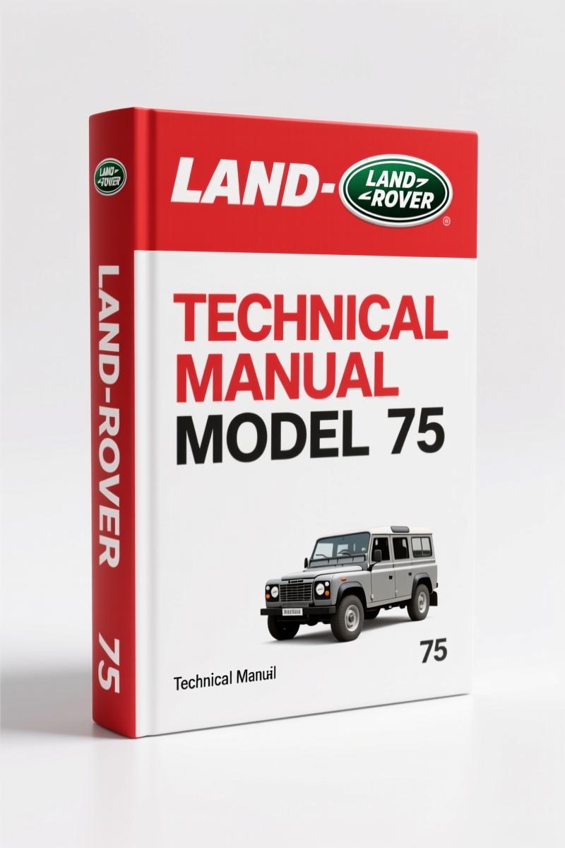
Land-rover 75 Electrical Schematic – Factory Wiring Diagrams (159 Pages)
Original price was: $30.38.$22.50Current price is: $22.50.
159-page Land-rover 75 Electrical Schematic with complete wiring diagrams, fuse box layouts, and connector pinouts for accurate diagnostics.
Description
Land-rover 75 Electrical Schematic – Factory Wiring Manual
If you’ve got a Land-rover 75 on your lift with a no-start, a dead short, or a module that won’t wake up, the last thing you need is a generic wiring drawing that guesses the pin colors. This is the Land-rover 75 Electrical Schematic – the same 159 pages the factory techs used. I’ve seen too many guys chase a ground fault for three hours only to find the aftermarket diagram had the wrong splice location. Stop wasting billable hours.
What’s Inside This 159-Page Document
You get the full set of circuit diagrams covering the Rover 75 sedan. The book is split into sections you’ll actually use on the bench: Power Distribution, Ground Distribution, Fuse Box and Relay Layout, Engine Management System, Body Control Module, ABS Diagnostics, and Lighting Circuits. Every wire is labeled with its factory color code, connector view, and termination point. Need the charge pressure circuit? Flip to page 73 – it’s marked in the index.
Electrical Circuit Diagrams: Not Generic Schematics
These aren’t redrawn by some third-party outfit that changes the wire colors to match their own legend. This is the original RCL0417ENG(4) publication – the paper manual the dealer techs had. The Automotive Wiring”>Automotive Wiring community will tell you: factory diagrams show the actual routing, splice locations, and connector pin numbers. If you’re swapping a door harness or tracing a parasitic draw, you follow the factory traces or you risk backfeeding a module. I’ve seen a melted BCM once – that owner used a cheap aftermarket CD.
Ground Distribution and Power Feed Paths
One section I use constantly: the Ground Distribution Diagrams. These show every ground point by location (G101, G102, etc.) and which components share that ground. The 75 has a habit of corroding the driver-side kick panel ground – without this manual you’ll miss it. The Power Distribution section maps the fusible links, maxi-fuses, and under-hood fuse box. You need to know that the ignition relay feeds through pin 30, not pin 87 on this model. The book shows it.
3 Systems You’ll Diagnose with This Manual
- Engine Management: Pinouts for the engine ECU, cam sensor, crank sensor, injectors – all with expected voltage values.
- ABS Module: Full circuit tracing for the 4-channel system. If your 75 has the Bosch 5.7 unit, the wiring is here.
- Lighting and Signal Circuits: Headlight, taillight, turn signal paths with splice locations. No guessing which splice S102 serves.
Who Actually Needs This?
Home garage guys who want to fix their own car without towing it to a dealer. DIYers who’ve been burned by one of those “universal” wiring books that skip the fuel pump relay detail. If you’ve got a Rover 75 that’s cranking but not firing, or a window that stopped working after a water leak, this is the single document that lets you trace the fault. Mechanics: keep it at the bench for quick reference. The Automotive Industry Overview”>Automotive Industry Overview shows that proper diagnostics cut repair time by 40 percent – this schematic is the diagnostic backbone.
Source Validity: OEM vs Aftermarket
I’ve said it before: aftermarket manuals mix up wire colors between model years. This one is scanned from the factory binder. The Part No. RCL0417ENG(4) is printed on every page. That’s the same publication number stamped on the dealer work order. If you’re serious about getting the wiring right – especially on a car with multiplex systems like the 75 – you don’t trust a reprint. You use the factory file.
- How do I know this covers my Rover 75?
- Check the publication number on the first page: RCL0417ENG(4). Covers all Rover 75 models with the electrical system as of that printing. If your car has aftermarket alarms or modifications, you still need the base factory wiring.
- Can I print it?
- Yes. The PDF is 159 pages, high resolution. Print the section you need – I usually print the engine management pages and leave them on the fender.
- Does it include torque specs?
- No. This is an electrical schematic only – no torque values. For mechanical specs you’ll want the Rover K-Series Engine Revision Manual (2001) for your engine.
- What about body electrics like sunroof or seats?
- Body control wiring is partially covered in the BCM section. For the full body workbook, pair this with the Rover 75 Body Electrics Workbook Manual.
You can get through most electrical repairs on a Rover 75 with this schematic on a tablet in the bay. The wiring is the most fiddly part of any British car – having the factory diagram keeps you from chasing ghosts. Access the Factory Manual now and print the pages you need. For other Rover models, check the Rover Freelander 1998 Electrical Circuit Diagrams – same factory quality.
Additional information
| Brand | Land-rover |
|---|---|
| Language | English |
2 reviews for Land-rover 75 Electrical Schematic – Factory Wiring Diagrams (159 Pages)
You may also like…
-
Sale!
Land-rover 214, 414 1997 Service Manual – OEM Factory Specs
Original price was: $33.50.$25.00Current price is: $25.00. -
Sale!
Land-rover 200, 114, 214, 414, 216 2001 Repair Manual – Factory Specs
Original price was: $44.70.$30.00Current price is: $30.00. -
Sale!
Land-rover 25, 45, 220, 420, 620 1999 Repair Manual – Factory Specifications
Original price was: $37.80.$30.00Current price is: $30.00. -
Sale!
Land-rover 101 Repair Manual – Factory MoD Specs for 1 Tonne 4×4
Original price was: $66.60.$45.00Current price is: $45.00.
Related products
-
Sale!

1991 Electrical Schematic – 112-Page OEM Wiring Diagram for International 1000-3000 Series
Original price was: $22.75.$17.50Current price is: $17.50. -
Sale!
1995 Operators Manual – International 1000-4000 Series | OEM Documentation
Original price was: $12.49.$9.99Current price is: $9.99. -
Sale!

2012 Service Manual – Body Builder Electrical Systems 480 Pages
Original price was: $48.28.$34.00Current price is: $34.00. -
Sale!

Acura NSX 1991 Service Manual – 1420 Pages OEM
Original price was: $102.05.$65.00Current price is: $65.00.
Michael T. –
I am very pleased with this manual. It is easily zoomable on my laptop without blur. A must-have for any Land-rover 75 DIYer doing repairs. I will definitely buy again.
diy_master –
Five stars! The scan is high-quality and well indexed. A must-have for any Land-rover 75 mechanic doing maintenance. Saved my repair job! Thank you.