
Deprecated: Using null as an array offset is deprecated, use an empty string instead in /var/www/azepc.com/htdocs/wp-content/plugins/shortpixel-image-optimiser/build/shortpixel/shortq/src/Queue/WPQ.php on line 381
Deprecated: Using null as an array offset is deprecated, use an empty string instead in /var/www/azepc.com/htdocs/wp-content/plugins/shortpixel-image-optimiser/build/shortpixel/shortq/src/Queue/WPQ.php on line 381
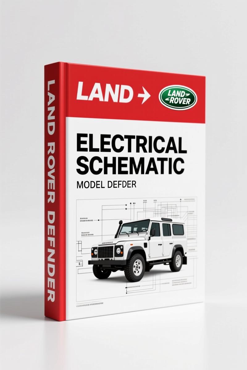
Land Rover Defender 1998 Electrical Schematic – Factory Wiring Diagrams & Connector Data
Original price was: $25.44.$16.00Current price is: $16.00.
OEM Land Rover Defender 1998 electrical schematic – 290 pages of factory connector data, fuse layouts, and GEMS engine management diagnostics.
Description
Land Rover Defender 1998 Electrical Schematic – Factory Wiring Document
If you have ever tried to trace a dead short in a Defender using a generic wiring diagram that was clearly scanned out of a high school shop class, you know the pain. Color codes that don’t match, connectors labeled wrong, missing earth points. That is why I keep the factory Land Rover Defender 1998 Electrical Schematic on the bench. 290 pages, straight from Rover Technical Communication in 1998. This is the same document the dealer techs used when these V8i trucks were still under warranty. No reprints, no aftermarket translation errors — just the original English, French, German, Italian, Spanish, and Portuguese text bundled into one PDF. If you are chasing a no-start on a GEMS system or a taillight that stays dark, this is where you start.
Connect Details Index: 196+ Connectors Mapped
The meat of this manual is the CONNECT DETAILS section running from C0001 all the way to C1217. Each connector gets its own page with pin assignments, wire gauge, and the exact color code stripe. Need to know what pin C0098 does for the heated rear window? Flip to that connector entry. The manual indexes them numerically so you do not waste time flipping through vague diagrams. This is what separates an OEM electrical schematic from a parts-store photocopy. Every ground header and earth point is listed under EARTH POINTS AND HEADER JOINTS on page 3.1. That section alone has saved me two hours on a Defender that had a corroded C0377 ground under the dash.
Does This Manual Cover the GEMS Engine Management?
It does. Section 4, DESCRIPTION AND OPERATION, includes a full breakdown of the GENERIC ENGINE MANAGEMENT SYSTEM (GEMS) starting on page 4.9. That covers the Diagnostic Socket, the ECM pinouts, and the starting/charging circuit. If your 1998 Defender V8i cranks but won’t fire, you need the GEMS section to test the injector drivers and crank sensor circuit. The manual also covers ENGINE IMMOBILISATION and the ANTI-THEFT ALARM — critical when the factory alarm decides to lock you out. I have seen aftermarket manuals skip the immobilizer logic entirely. This one does not.
5 Sections of Factory Electrical Data
The manual is organized into five major sections: INTRODUCTION (wire colour codes, abbreviations, electrical precautions), FUSE DETAILS (engine compartment and passenger compartment fuse boxes), EARTH POINTS AND HEADER JOINTS, DESCRIPTION AND OPERATION (all the subsystems), and the massive CONNECT DETAILS index. Each section is numbered consistently. The fuse box diagrams on page 2.1 show the exact amperage and cavity layout for the Defender V8i — not the NAS spec, not a diesel version. The WIRE COLOUR CODES page 1.9 gives you the Land Rover code system so you can read the striped wires correctly. Aftermarket diagrams often use generic colors that do not match reality. This manual uses the actual factory codes: N (Brown), U (Blue), R (Red), and so on.
Start with the Electrical Precautions on Page 1
Before you probe anything, read the ELECTRICAL PRECAUTIONS at the front. It tells you the proper disconnect procedure for the battery, the safe way to backprobe connectors, and the torque for battery terminal nuts. Yes, there is a torque spec for the battery clamp in an electrical manual. That is the level of detail Rover put into this. If you have a multimeter and a test light, you can diagnose any circuit in the Defender using this document. I recommend printing out the connector pages for the circuit you are working on — it keeps grease off your tablet.
Earth Points and Header Joints: Where Grounding Goes Wrong
The EARTH POINTS section on page 3.1 lists every ground location on the vehicle. Corroded grounds are the number one cause of intermittent electrical problems on older Defenders. The manual shows the exact fastener size, the wire gauge to each ring terminal, and the location (e.g., left inner wing, behind headlamp). If your instrument cluster flickers or the starter solenoid clicks but the engine doesn’t spin, check earth point E003. The manual tells you which connectors tie into that ground. Pair this manual with the Land Rover Defender MY2007 Workshop Manual for mechanical procedures, or the Land Rover Defender Electrical Reference Library for additional circuit diagrams. For the TDI crowd, the Land Rover Defender 300Tdi 1996 Workshop Manual covers the diesel drivetrain. For background on electrical system design in off-road vehicles, see Automotive Industry Overview. And if you need replacement battery specs, check Automotive Battery.
- Is this manual a reprint of aftermarket diagrams?
- No. It is a direct scan of the 1998 Rover Technical Communication publication LRL 0190ENG.
- What torque specs does it include?
- This manual is an electrical schematic — it does not list torque values for engine or suspension components. It contains battery terminal clamp torque and connector retainer torque. If you need head bolt or driveline torque specs, you need the corresponding workshop manual. That said, the electrical system is covered down to the last pin. The GEMS diagnostic socket, the heated rear window relay, the wiper park switch — every circuit is mapped. For torque values on mechanical parts, grab the workshop manual from our catalog.
You have a 1998 Defender V8i that you want to keep running without gambling on burned-out relays? Then you need the factory wiring on your screen or in your toolbox. Access the Factory Manual from AutoRepairManuals and get back to fixing instead of guessing.
Additional information
| Brand | Land Rover |
|---|---|
| Language | English |
4 reviews for Land Rover Defender 1998 Electrical Schematic – Factory Wiring Diagrams & Connector Data
You may also like…
-
Sale!
Land Rover Defender 1996 Workshop Manual – Factory Specs for 300Tdi
Original price was: $63.20.$40.00Current price is: $40.00. -
Sale!
Land Rover Defender 2007 Electrical Schematic – 338-Page OEM Circuit Data
Original price was: $53.20.$40.00Current price is: $40.00. -
Sale!
Land Rover Defender Workshop Manual – 1213 Pages of Factory Specs
Original price was: $62.80.$40.00Current price is: $40.00. -
Sale!
Land Rover Freelander 2003 Wiring Diagram – Factory Electrical Schematics
Original price was: $58.95.$45.00Current price is: $45.00.
Related products
-
Sale!

1992 Electrical Schematic – OEM Wiring Diagrams for International 1000-3800
Original price was: $24.48.$18.00Current price is: $18.00. -
Sale!
1991 Electrical Schematic – 112-Page OEM Wiring Diagram for International 1000-3000 Series
Original price was: $22.75.$17.50Current price is: $17.50. -
Sale!
1996 Operators Manual – International 1000-4000 Series (246 pages)
Original price was: $15.28.$9.99Current price is: $9.99. -
Sale!

2011 Parts Catalog – International 7400 SFA 6X6 – 1886 Pages of OEM Part Numbers
Original price was: $32.00.$25.00Current price is: $25.00.
Michael T. –
This is exactly what I was looking for. Instant access after payment. Contains precise wiring diagrams for Land Rover. Saves me hundreds of money.
workshop_guy –
Highly recommended! The file is very clear. A must-have for any Land Rover Rover owner doing maintenance. Great value for money.
Charles W. –
Five stars! The file is very clear. It helped me to troubleshoot my Land Rover Rover transmission. Saved my weekend project! Thanks.
Richard G. –
Great OEM spec sheet. The text is searchable and easy to navigate. It helped me to repair my Land Rover Rover electrical system. I will definitely buy again.