
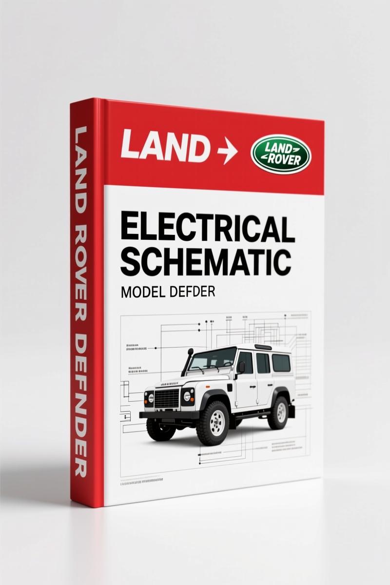
Land Rover Defender 2001 Wiring Diagram – OEM Electrical Schematics
Original price was: $20.96.$16.00Current price is: $16.00.
OEM Land Rover Defender 2001 Wiring Diagram: 118 pages covering Td5 and 300 Tdi electrical systems, ABS, fuel pump, and engine management.
Description
Had a Defender come in last week with a no-crank that traced back to a corroded splice in the Td5 charging circuit. Without the factory wiring diagram I’d have been swapping alternators and batteries for half a day. The Land Rover Defender 2001 Wiring Diagram from AutoRepairManuals is the exact 118-page PDF that Land Rover techs used when these trucks were still in warranty. It’s not a reprint of a third-party interpretation—it’s the OEM publication part number LRL 0452ENX, with color codes and circuit paths that match the actual harness in your bay. If you’ve ever chased a ghost draw on a Defender with aftermarket Chilton garbage, you know why this matters.
Power Distribution: 300Tdi and Td5
The manual splits power distribution into two clear sections: one for the 300Tdi, one for the Td5. Page 1 of the electrical circuit diagrams shows the main feed from the battery to the starter solenoid and fusebox. Both diesel variants get separate pages so you aren’t guessing which relay feeds which glow plug. I’ve seen guys run a parallel feed to the Td5 ECU using a 300Tdi schematic—that’s how you melt a 50-amp fuse link. The factory layout shows exactly where the Td5 engine management relay sits and which pin on the fuse box it calls home.
Earth Distribution and Ground Points
Ground loops are the number one cause of intermittent dash lights on these trucks. This manual dedicates a full section to earth distribution, listing every ground stud and ring terminal location from the chassis rail behind the battery to the inner wing. It even spells out the thread size—M6 where most guys guess M8. Follow the factory ground path and you won’t spend two hours tracing a sagging voltage drop that turns out to be a corroded bolt.
ABS Diagnostics: Factory Procedure
The anti-lock braking system on the Td5 Defender is a separate controller with its own power and ground feeds. The wiring diagram shows the ABS ECU pinout, the wheel speed sensor circuits (front and rear), and the modulator valve connections. If you’re seeing an ABS light that won’t clear, this is the map to test continuity at the sensor rings without pulling apart the whole harness. I’ve used it to find a broken wire inside the loom near the left rear damper—saved the customer the cost of a new controller.
Fuel Pump Wiring – Td5 – What the Manual Covers
The Td5 fuel pump lives inside the tank and is driven by a dedicated relay and fuse. The manual shows the pump circuit from the ECM through the inertia switch to the pump itself. One common failure is the pump cutting out after a hard bump because the inertia switch trips. The diagram pinpoints that switch on the transmission tunnel. An aftermarket diagram would lump it into “fuel system,” but the OEM layout lists it as a separate node with the correct wire colors (pink/black for the trigger, green/white for the pump feed).
Charging and Starting – Two Engines, Two Schematics
You get separate charging and starting diagrams for the Td5 and 300Tdi. The 300Tdi uses a simpler pre-engaged starter with a solenoid pull-in wire; the Td5 has a PCM-controlled start relay. If you swap a 300Tdi starter into a Td5 without adjusting the control circuit, you’ll crank until the battery dies because the PCM never sees an engine speed signal. The schematic on [needs page reference] explains the interlock. The manual also covers the overspeed warning system—something most DIY guys don’t even know exists on these trucks. A wiring issue there can kill the engine at highway speeds.
3 Reasons to Choose OEM Documentation Over Aftermarket
First, the color codes are printed on page 3 in seven languages—no translating “red/yellow” to “RJ” because some generic publisher forgot to translate the legend. Second, the manual includes splice and centre tap locations (look for HEADER JOINTS and SPLICES AND CENTRE TAPS in the TOC). Those are the hidden failure points. Third, the trailer socket wiring is right there in the back, which saves you from chasing a broken brake light relay that’s actually a corroded 7-pin connector. I would not own a Defender without this on my tablet.
Does This Manual Cover the 2001 Defender Only?
The publication year is 2001, and the diagrams are labeled “Defender 2002 Electrical Circuit Diagrams – English Export” in the header, so you’re getting late-2001 model year data. If you need earlier Td5 or 300Tdi specifics, look at the Land Rover Defender MY2007 Workshop Manual or the Land Rover Defender Electrical Reference Library for cross-model coverage. The Land Rover Defender 300Tdi 1996 Workshop Manual covers the older engine bay layouts. For a deeper understanding of wiring fundamentals, the Automotive Wiring resource explains how manufacturers design these systems, and the Automotive Industry Overview gives context on why OEM diagrams are built the way they are.
- What torque specs are included in this wiring diagram?
- None. This is a wiring diagram, not a service manual. It covers circuits, connectors, and ground points. For torque values you need the workshop manual.
- I have a non-running Td5 with no power to the ECM. Where do I start?
- Open the ENGINE MANAGEMENT SYSTEM – Td5 section. It maps the ECM power and ground pins, the diagnostic socket, and the main relay circuit. Check continuity from the ECM relay output (pin 87) to the ECM’s main power pin (pin 1 on the 55-pin connector). The fuel pump circuit also runs through that relay; if the pump isn’t priming, don’t replace the pump—replace the relay first. I’ve seen three Defenders this year with a bad ECM relay that fixed the no-start. The diagram also shows the link between the immobilisation unit and the ECM. If the security system doesn’t deactivate, the ECM stays dead. Trace that wire (usually a purple/green) back to the alarm module. Factory diagrams are the only way to see that cross-connection without digging through the entire harness.
Access the Factory Manual from AutoRepairMuals and keep it on your workbench or tablet. When you’re under the dash of a 20-year-old Defender, having the OEM wire colors and splice locations is the difference between a half-day diagnosis and a half-hour fix.
Additional information
| Brand | Land Rover |
|---|---|
| Language | English |
4 reviews for Land Rover Defender 2001 Wiring Diagram – OEM Electrical Schematics
You may also like…
-
Sale!
Land Rover Defender 1996 Workshop Manual – Factory Specs for 300Tdi
Original price was: $63.20.$40.00Current price is: $40.00. -
Sale!
Land Rover Freelander 2003 Wiring Diagram – Factory Electrical Schematics
Original price was: $58.95.$45.00Current price is: $45.00. -
Sale!
Land Rover Defender 2007 Electrical Schematic – 338-Page OEM Circuit Data
Original price was: $53.20.$40.00Current price is: $40.00. -
Sale!
Land Rover Defender Workshop Manual – 1213 Pages of Factory Specs
Original price was: $62.80.$40.00Current price is: $40.00.
Related products
-
Sale!

1989 Service Manual – International 2000-8000 Electrical Systems
Original price was: $72.00.$50.00Current price is: $50.00. -
Sale!

1993 Electrical Schematic – International 1000/3000/4000 Bus Chassis OEM Wiring Diagrams
Original price was: $29.26.$22.00Current price is: $22.00. -
Sale!

2011 Parts Catalog – International Truck OE Parts Documentation (1786 Pages)
Original price was: $34.50.$25.00Current price is: $25.00. -
Sale!
1992 Electrical Schematic – OEM Wiring Diagrams for International 1000-3800
Original price was: $24.48.$18.00Current price is: $18.00.
John S. –
Excellent workshop guide. The PDF is very clear. A must-have for any Land Rover Rover DIYer doing maintenance. Saves me so much dollars.
gearhead88 –
This is just what I needed. The file quality is excellent. Every spec sheet is provided for Land Rover Rover. I will recommend this shop to others.
pro_mechanic –
This is just what I was looking for. Instant access after checkout. A must-have for any Land Rover Rover mechanic doing repairs. Saved my repair job! Thank you.
Charles W. –
I am very pleased with this purchase. The scan is high-quality and well indexed. A must-have for any Land Rover Rover DIYer doing repairs. Saved my weekend project! Thanks.