
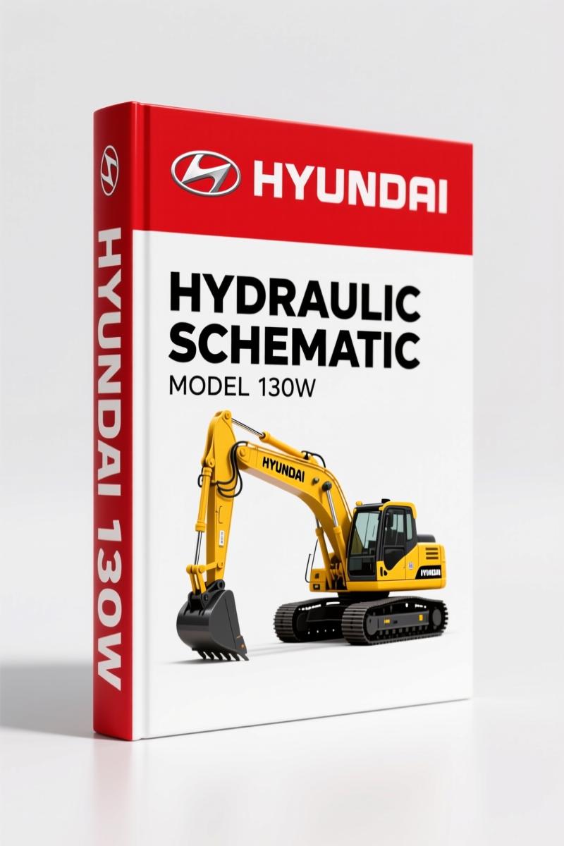
Hyundai 130W Hydraulic Schematic – 28 Pages Factory Circuit Diagrams
Original price was: $22.42.$15.25Current price is: $15.25.
28-page OEM hydraulic schematic for Hyundai 130W. Includes component identification, pilot circuit flow, and pressure settings. Factory-certified.
Description
Hyundai 130W Hydraulic Schematic – What You Get on the Bench
If you’re staring at a Hyundai 130W that won’t lift, stalls under load, or leaks pressure from a dozen ports, you need the Hyundai 130W Hydraulic Schematic—not a generic diagram from some third-party site. I’ve watched guys chase air in the pilot circuit for two hours because they were reading an aftermarket drawing with missing check valves. This OEM file came straight from Hyundai’s engineering group. It shows exactly how the main pump, control valve, swing motor, and travel motor tie together. 28 pages of circuit layouts and component callouts. No fluff. No reprints. No guesswork.
Hydraulic Circuit Layout: What’s on Page 1
Page 1 lists the GROUP 1 HYDRAULIC CIRCUIT with 47 components—every pump, valve, cylinder, filter, and accumulator numbered. You get main pump (1), main control valve (2), swing motor (3), travel motor (4), both RCV levers, accelerator pedal, turning joint, transmission valve, steering valve, gear pump, locking valve, brake supply valve, accumulators (17–19), shuttle valve, RCV lever-dozer, oscillating cylinder, check valves (23–24), oil cooler, strainer, bypass valve, return filter, spin filter, air breather, hydraulic tank, line filter, boom cylinders (RH/LH), arm cylinder, bucket cylinder, last guard filter, brake valve, five pressure switches, solenoid valve, dozer cylinders (RH/LH), and gauge block. If you need to locate the line filter or spin filter in the circuit, this page gets you there without flipping through a hundred pages.
Pilot Circuit Pressure: Why 40 kg/cm² Matters
Page 3 of the schematic covers the pilot circuit—suction, delivery, and return. The pilot pump draws oil from the hydraulic tank through a suction filter, then discharges through the line filter to the safety lock solenoid valve, then to the remote control valves. Hyundai specifies a relief valve setting of 40 kg/cm² (about 569 psi). That number is critical. Set it lower and the RCV levers won’t shift the spools fully; set it higher and you risk blowing the seals in the swing parking brake or the solenoid valves. The diagram also shows the flow path through the EPPR valve, solenoid valve assemblies, and the main control valve. You’ll see exactly where the pressure drops and where the return oil goes back to the hydraulic tank via the spin filter.
Suction, Delivery, and Return Circuit Explained
On page 3 you’ll find the full schematic for the suction, delivery, and return circuit. The pilot pump feeds oil through the line filter, then branches to the safety solenoid valve, the swing motor brake supply, the gear pump, and the transmission valve. Each branch is labeled with port designations like Pg, Pi, dr1–dr14. If you’re troubleshooting a brake that won’t release or a travel motor that drifts, trace the dr6, dr5, dr3, dr4 lines on the diagram—they control the dozer, arm, boom, and bucket circuits. The schematic even includes the gauge block location for pressure testing.
3 Critical Checks Before Pressurizing the Hydraulics
First, verify that the safety lock solenoid valve is in the correct position. When the lever is moved downward, oil flows to the RCVs; when upward, it blocks flow. The manual shows both states on page 4. Second, confirm the line filter is clean—any restriction here drops pilot pressure and causes erratic lever response. Third, check the accumulators (17–19) for precharge. The schematic labels them, but the factory spec for precharge is not in this document—you’ll need the full service manual for that. But the circuit diagram tells you where they sit in relation to the brake supply valve and shuttle valve.
Who Needs This Schematic?
Home garage mechanics who maintain their own heavy equipment. Small workshop owners who see Hyundai loaders coming in with hydraulic complaints. Anyone who has ever wasted a Saturday swapping a pump that wasn’t the problem because the real issue was a stuck check valve in the pilot circuit. This schematic gives you the actual flow paths and component numbering so you can test, isolate, and replace with confidence. It’s not a repair manual—it’s the hydraulic roadmap that should sit on your toolbox while you work.
If you’re also working on related Hyundai equipment, check the Hyundai Seasall D170 & D150 Installation Manual, the Hyundai Kia A4CF1 M5CF1 M5CF2 M5CF3 M6GF2 Training Manual – 25 Pages, and the Hyundai Heavy Industries Europe 7, 7A 2007 Service Manual – Factory Specs. For a broader look at hydraulic systems in construction equipment, see this Automotive Industry Overview and understand how Automotive Battery power interacts with electrical solenoids in the circuit.
- Does this schematic include torque specs for hydraulic fittings?
- No. This is a circuit diagram—it shows flow paths, component locations, and port labels. Torque specs for fittings are in the factory service manual, not the schematic.
- Can I use this to replace a hose on the boom cylinder?
- Yes. Page 1 shows boom cylinder (RH) and (LH) as components 33 and 34. The schematic traces the lines from the main control valve to those cylinders. You’ll see which ports connect to which valves.
- What is the pilot relief pressure?
- 40 kg/cm² (approximately 569 psi). Set on the relief valve integrated with the pilot pump. The schematic on page 3 shows the relief valve and the pilot pump in the suction/delivery circuit.
- How many pages and what format is the file?
- 28 pages. PDF format, originally scanned from Hyundai’s factory engineering documents. No watermarks, no missing pages.
You need the Hyundai 130W Hydraulic Schematic on your bench if you’re deep into hydraulic diagnostics. It cuts through guesswork and gives you the factory diagram. Access the Factory Manual now and get back to turning wrenches.
Additional information
| Brand | Hyundai |
|---|---|
| Language | English |
3 reviews for Hyundai 130W Hydraulic Schematic – 28 Pages Factory Circuit Diagrams
You may also like…
-
Sale!

Hyundai HD65, HD72, County Training Manual – A/C Diagnostics
Original price was: $65.00.$50.00Current price is: $50.00. -
Sale!
Hyundai HDF15-5, HDF18-5 Service Manual – 227 Pages
Original price was: $61.65.$45.00Current price is: $45.00. -
Sale!
Hyundai HDF50III, HDF70III Service Manual – Factory Repair Specs
Original price was: $70.20.$45.00Current price is: $45.00.
Related products
-
Sale!

2004 Acura TSX Wiring Diagram – 73-Page Factory Electrical Schematics
Original price was: $15.88.$9.99Current price is: $9.99. -
Sale!

Acura Integra 1998 Service Manual – 1891 Pages Factory OEM Documentation
Original price was: $31.75.$25.00Current price is: $25.00. -
Sale!

1991 Electrical Schematic – 112-Page OEM Wiring Diagram for International 1000-3000 Series
Original price was: $22.75.$17.50Current price is: $17.50. -
Sale!

Service Manual – International HS 2.8L Engine – 130 Pages of Factory Specs
Original price was: $56.40.$40.00Current price is: $40.00.
David K. –
I am very pleased with this transaction. The file is high resolution. A must-have for any Hyundai 130W mechanic doing repairs. Great value for money.
diy_master –
I am so happy with this manual. It is very easy to read on my laptop without losing quality. A must-have for any Hyundai 130W mechanic doing repairs. Great value for money.
Robert M. –
Great OEM spec sheet. It is easily zoomable on my laptop without blur. Every torque spec is included for Hyundai 130W. I will definitely buy again.