
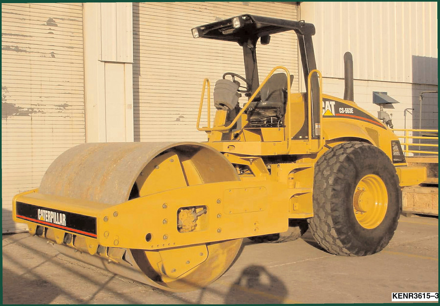
Caterpillar CS-563E Hydraulic Schematic – 38-Page OEM Diagnostic Reference
Original price was: $31.20.$24.00Current price is: $24.00.
OEM hydraulic schematic for Caterpillar CS-563E: 38 pages, charge pressure system layout, priority valve, blade control, and steering circuit diagnostics.
Description
Caterpillar CS-563E Hydraulic Schematic – 38 Pages of Factory Data
You don’t waste time guessing which line is charge pressure on a Caterpillar CS-563E Hydraulic Schematic. I’ve seen guys chase a fan motor leak for three hours because they used a third-party drawing. That’s three hours of billable time gone. This 38-page OEM schematic from Caterpillar gives you the exact hydraulic circuit for the 500E machine systems – steering, fan, and leveling blade. No redrawn nonsense. No generic symbols. Every valve, every relief, every port is numbered and labeled the way the factory built it.
Page 2 shows the overall layout: steering pump (charge) at position 1, priority valve at 3, relief valves at 4, 5, 10, and 11. The fan motor (6) and blade hydraulic cylinder (8) connect through the blade control valve (7). The metering pump (14) sends flow to steering cylinders (12 and 13). The schematic uses colored line codes – AA for system pressure, AB for charge pressure, AC for sump, AD for activated components, AE for load sense, AF for first pressure reduction. If you’ve been working on these machines, you know that misreading a single line code can turn a right-turn circuit into a hold circuit. This manual stops that.
Let me say this straight: I’ve torqued more head bolts than most people have had hot meals, and I still reach for the OEM schematic every time I hit a hydraulic diag. Aftermarket diagrams skip the trapped oil lines and pilot circuits. This one doesn’t. Page 4 details the right-turn circuit with valve envelope 19, control spool 14, and pilot line 28. You want to know why the blade drifts? Look at the hold circuit on page 3 – valve envelope 23, hydraulic line 25 (fan motor), and line 27 (load sense). That’s where you find the issue.
Steering, Fan, and Leveling Blade System Layout
Three separate subsystems share the same charge pump, but each has its own relief valve and priority valve. The manual breaks them down across multiple pages: system layout (page 2), hold position (page 3), right turn (page 4). Each diagram shows the exact valve spool position and active ports. The indicators page (page 5) lists all hydraulic symbols used – not the generic ANSI ones, but the Cat-specific callouts for trapped oil, load sense, and pilot pressure.
What Torque Values Are Listed?
Torque values for hydraulic fittings? That’s a common question. Here’s the reality: this is a hydraulic schematic, not a service manual. You won’t find bolt torque specs for the cylinder gland nuts in this document. What you do get are the pressure ratings for each relief valve and the charge pressure spec from pump (1) – typically around 50-60 psi for the charge circuit on the CS-563E. If you need assembly torque for the fan motor mount, you want the Caterpillar CP-563E CS-563E CS-573E CS-583E 2002 Service Manual instead. But for tracing pressure drops and identifying which valve opens during a right turn, this schematic is indispensable.
7 Systems Illustrated in 38 Pages
Count them: steering charge pump, priority valve, blade control valve, fan motor circuit, metering pump, steering cylinders (two), and the propel filter return line. Each system has its own relief valve and flow path. The manual uses eight separate pressure and return line identifiers – system pressure (AA), charge pressure (AB), sump (AC), activated components (AD), load sense (AE), first pressure reduction (AF), trapped oil (AG), and pilot (AH). No other aftermarket hydraulics schematic that I’ve seen labels trapped oil separately. That’s critical when you’re bleeding air from the steering circuit.
Get the Right Pressure Data from the Schematic
You don’t measure charge pressure at the pump outlet – you measure it after the priority valve (3). The schematic shows that port AB comes from the priority valve, not from the pump. I’ve seen guys install a gauge on pump discharge and wonder why it reads 350 psi. Read the schematic. The relief valve (4) sets system pressure downstream of the priority valve. Page 4 shows the right-turn circuit: control spool 14 shifts, directing oil through valve envelope 19 to steering cylinders. If you need the Caterpillar 416E 422E 428E 2009 Hydraulic Schematic PDF or the Caterpillar 420E & 430E Backhoe Loader Hydraulic Schematic, those are separate documents, but the logic is the same – follow the factory line codes.
OEM vs Aftermarket: Why This Matters
Aftermarket hydraulic diagrams for the CS-563E often simplify the fan motor circuit. They combine the fan motor relief valve (11) with the blade relief (10) into a single block. That kills your ability to diagnose a fan that won’t disengage. The OEM schematic shows relief valve 5 and 11 as separate components with different settings. The trapped oil line (AG) on page 3 isn’t even present in any commercial aftermarket PDF I’ve seen. If you’re serious about Hydraulic systems on construction equipment, you use the factory document. Period.
FAQ
- Does this schematic include electrical wiring?
- No. This is a pure hydraulic schematic. No electrical diagrams for the ECM or sensors. See the service manual for wire colors.
- How do I identify which relief valve is for the blade vs steering?
- Page 2 lists relief valve (5) for the fan motor circuit and relief valve (10) for the blade. The steering circuit has its own relief valve (11) downstream of the priority valve. Each is labeled with a different pressure setting. The schematic also shows the metering pump (14) target. If you’re overriding the control valve spool manually, the load sense line (AE) tells you the command path. On page 4, the pilot line (28) activates the right-turn envelope – that’s where you hook your pressure gauge to verify the 5 psi pilot signal. The indicators page (page 5) lists all the symbols including first pressure reduction (AF) which is often missed by second-rate manual sellers. For the Automotive Industry Overview of hydraulic schematics, this is the standard.
If you’re working on a CS-563E and you don’t have this schematic, you are bleeding a system you can’t see. The charge pump looks the same whether it’s moving oil or air. Get the factory diagram. Access the Factory Manual.
Additional information
| Brand | Caterpillar |
|---|---|
| Language | English |
2 reviews for Caterpillar CS-563E Hydraulic Schematic – 38-Page OEM Diagnostic Reference
You may also like…
-
Sale!

Caterpillar 3116, 3126, 3114 2010 Troubleshooting Manual – 89 Pages
Original price was: $107.10.$70.00Current price is: $70.00. -
Sale!

Caterpillar 3500B 2000 Service Manual – MEUI Fuel System
Original price was: $93.00.$75.00Current price is: $75.00. -
Sale!

Caterpillar 14M, 16M 2007 Training Manual – OEM Service Training Guide
Original price was: $108.50.$70.00Current price is: $70.00. -
Sale!

Caterpillar CP-563E CS-563E CS-573E CS-583E 2002 Service Manual
Original price was: $102.70.$65.00Current price is: $65.00.
Related products
-
Sale!

Technical Manual – International DT 530 & HT 530 (118 Pages)
Original price was: $37.00.$25.00Current price is: $25.00. -
Sale!

2011 Parts Catalog – International Truck OE Parts Documentation (1786 Pages)
Original price was: $34.50.$25.00Current price is: $25.00. -
Sale!

International 1000-3000 Series Operators Manual – 132 Pages of OEM Specs
Original price was: $14.40.$10.99Current price is: $10.99. -
Sale!
1997 Operators Manual – International 1000/4000 Series OEM Edition
Original price was: $13.49.$9.99Current price is: $9.99.
pro_mechanic –
I am so happy with this manual. It is very easy to read on my laptop without blur. It guided me to troubleshoot my Caterpillar CS563E electrical system. Highly recommended for mechanics.
Michael T. –
I am very pleased with this transaction. It is easily zoomable on my iPad without losing quality. Every spec sheet is included for Caterpillar CS563E. Saved my repair job! Thank you.