
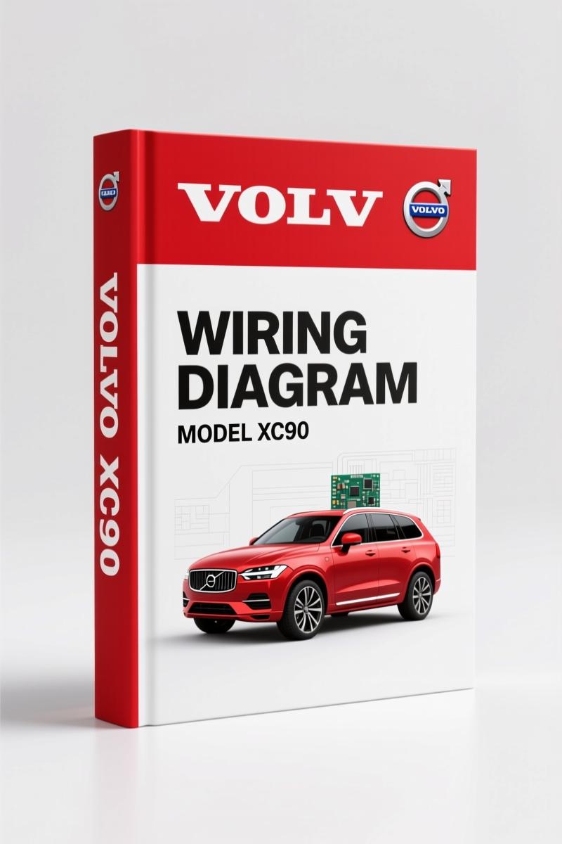
Volvo Penta XC90 2010 Wiring Diagram – 157 Pages of Factory Electrical Specs
Original price was: $30.80.$20.00Current price is: $20.00.
Factory-certified wiring diagram for Volvo Penta XC90 2010. 157 pages of OEM electrical schematics, fuse layouts, and diagnostic protocols.
Description
Volvo Penta XC90 2010 Wiring Diagram
I have spent 28 years under hoods, and there is one thing that gets my blood boiling faster than a stripped bolt: a wiring diagram that was photocopied twice and missing three pages. This Volvo Penta XC90 2010 Wiring Diagram is the real deal – 157 pages of factory-issued electrical documentation, not some aftermarket rewrite. It covers everything from the engine compartment fuses to the SRS/airbag circuits that will kill you if you guess wrong. You need the exact pinout for the Central Electronic Module (CEM)? It is in here. You want to trace the high-speed CAN bus without shorting something? Page 73 gives you the signal paths. This is the same manual Volvo dealerships used. No shortcuts.
157 Pages of Factory Wire Routing
Every wiring diagram in this manual is original Volvo Penta material. You get the full electrical distribution system – how power gets from the battery to the rear electronic module (REM). The fuse tables are broken down by location: engine compartment 11A/1-5, passenger compartment 11C/1-4, cargo compartment 11E/1-7. Each fuse is labeled with its amp rating and circuit. No generic “radio” labels – it says exactly which fuse feeds the audio amplifier vs. the infotainment system.
SRS and Airbag System: Why This Manual Is Your Safety Net
Page 2 of the manual starts with a warning that should be tattooed on your forearm: “Be especially careful when working on or around SRS, SIPS, and IC components.” That means the airbag system, side-impact protection, and inflatable curtain. If you bypass the proper disconnection procedure, you get a face full of pyrotechnic. This manual tells you exactly where the SRS sensors are, how to ground components before touching them, and which wires to never pierce. The test terminal location (data link connector) is shown. Do not touch a 2010 XC90 airbag without these pages open.
Fuse Boxes and Relay Locations – Real Module IDs
You want to know which relay in the engine compartment FMA1-FST3 controls the cooling fan? The manual breaks down every relay panel, including the cargo compartment relays and the ignition switch relay. Ground connections are mapped from 31/1 through 31/121 – that is over 100 ground points with their physical locations. The central electronic module (CEM) fuses F1-F11 and F15-F34 are listed with their actual circuit assignments. The rear electronic module (REM) fuses F1-F7 through F29-F38 are also there. If your left tail light is dead, you can pinpoint the fuse and the ground without tearing out the whole cargo trim.
Engine Management Systems Covered – Diesel, 5-Cyl, 6-Cyl, 8-Cyl
Group 23 in the TOC covers the fuel system and engine management for all four engine variants: diesel, 5-cylinder turbo, 6-cylinder, and 8-cylinder. Each one has its own wiring schematic. The 5-cyl turbo diagrams show the MAF sensor, injector pulse, and camshaft position signal. The diesel section includes the glow plug relay and fuel pressure regulator. If you are swapping a engine or chasing a no-start, you need the engine control module pinout from this manual. Also included: emission control diagrams for each engine, group 26 cooling fan circuits, and group 27 cruise control wiring.
What a DIY Mechanic Should Know Before Opening the Hood
This is not a repair manual – it is a wiring diagram. If you are a home garage guy who does not know how to read a schematic, you will struggle. But if you own a multimeter and have basic electrical knowledge, this manual saves you hours of chasing ghosts. The manual includes an explanation section on how to read the diagrams (pages 6-7) with abbreviations like “CEM” and “REM” defined. The data communication section covers high-speed CAN, low-speed CAN, LIN bus, and MOST bus – all the networks that talk between modules. You need to diagnose a parking camera failure? Group 39 shows the camera wiring with the Accessory Electronic Module (AEM). The 12V outlet, towbar harness (4/7/13 pin), and USB accessory unit are all mapped.
Source Validity: Factory Volvo, Not Aftermarket Rework
I have seen aftermarket manuals that combine three model years into one book and change pin colors because someone did not update the printer. This is factory original – part number TP 39151201, dated 2010, published by Volvo Car Corporation. The cover clearly says “WIRING DIAGRAM 2010” and the manual states: “Changes introduced up to and including January 2009 are included.” If you need later updates, you check service bulletins. But for 2009 and earlier production, this is the final word. The PDF is scanned from the original dealer binder, not re-typeset. Every connector shape, every wire gauge in the original.
Need to pair this with related model years? Check out the VOLVO V70 XC90 2008 Wiring Diagram for earlier models, or the Volvo XC90 2011 Wiring Diagram – Section: Group 35 Lighting if your truck is a year newer. For Volvo Penta marine engines, see the Volvo Penta FE 2009 Wiring Diagram – Factory OEM Manual. For general electrical theory, Automotive Wiring and Automotive Wiring are decent references, but they do not have the specific pinouts.
- Does this manual cover the SRS/airbag system in detail?
- Yes. Page 2 has a full warning section. The manual covers SRS, SIPS bag, and Inflatable Curtain (IC) systems. It includes sensor locations and grounding procedures.
- Can I use this to install an aftermarket stereo?
- You can find the audio wiring in Group 39 – external/internal amplifier, infotainment, Bluetooth handsfree. But the diagrams are factory wiring. If you are splicing into CAN bus, you need to understand the network. The manual shows the LIN and MOST bus, but aftermarket integration is your own risk.
- What engines are covered in the wiring diagrams?
- Group 23 includes engine management for 5-cylinder turbo, 6-cylinder, 8-cylinder, and diesel. Each has its own schematic with injector, ignition, and sensor pinouts. The diesel section is separate from the gas engines.
- Are the torque specs included for electrical connections?
- No. This is a wiring diagram manual. Torque specifications for mechanical fasteners are in the service manual, not here. What you get are fuse ratings, relay assignments, wire colors, and connector pin numbers. If you need head bolt torque, buy the engine service manual.
You have the wiring, the fuses, the modules, and the safety warnings. Now stop cross-referencing three different websites and get the real document on your screen. Access the Factory Manual and get back to work.
Additional information
| Brand | Volvo Penta |
|---|---|
| Language | English |
4 reviews for Volvo Penta XC90 2010 Wiring Diagram – 157 Pages of Factory Electrical Specs
You may also like…
-
Sale!

Volvo Penta TD520GE, TAD520GE, TD520VE, TD420VE, TAD420VE 2007 Workshop Manual
Original price was: $64.00.$50.00Current price is: $50.00. -
Sale!
Volvo Penta FH, FM Technical Manual – Factory Specifications for Suspension & Emissions
Original price was: $79.00.$50.00Current price is: $50.00. -
Sale!
Volvo Penta B7, B9, B12 2007 Wiring Diagram – Factory Electrical Schematics
Original price was: $71.10.$45.00Current price is: $45.00. -
Sale!
Volvo Penta D12A, D6B, D12C Technical Manual – 23-Page Factory Abbreviation Reference
Original price was: $67.50.$50.00Current price is: $50.00.
Related products
-
Sale!

1993 Electrical Schematic – International 1000/3000/4000 Bus Chassis OEM Wiring Diagrams
Original price was: $29.26.$22.00Current price is: $22.00. -
Sale!
1994 Troubleshooting Manual – International 1000-4000 FBC
Original price was: $60.00.$50.00Current price is: $50.00. -
Sale!
1992 Electrical Schematic – International 1000/3000/4000/2554 OEM Wiring Diagrams (132 Pages)
Original price was: $26.40.$20.00Current price is: $20.00. -
Sale!

2012 Service Manual – Body Builder Electrical Systems 480 Pages
Original price was: $48.28.$34.00Current price is: $34.00.
workshop_guy –
Superb resource! The scan is high-quality and easy to navigate. A must-have for any Volvo Penta Penta mechanic doing maintenance. Saves me a lot of money.
John S. –
I am so happy with this manual. It is very easy to read on my phone without losing quality. Contains precise wiring diagrams for Volvo Penta. Worth every penny.
David K. –
I am so happy with this manual. Instant access after checkout process. Contains precise wiring diagrams for Volvo Penta. Saved my repair job! Thank you.
Thomas B. –
Superb resource! It is very easy to read on my phone without losing quality. It assisted me to rebuild my Volvo Penta Penta engine. Great value for money.