
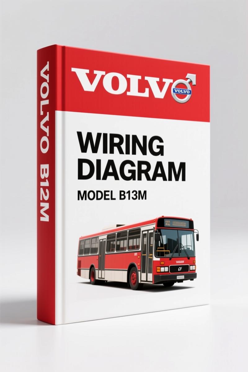
Volvo Penta B12M 2001 Wiring Diagram – Pneumatic & Brake Schematics
Original price was: $45.50.$35.00Current price is: $35.00.
Factory 30-page pneumatic diagram for Volvo Penta B12M 2001. ABS, suspension, brake circuits. Official Volvo Bus Corporation schematic.
Description
Volvo Penta B12M 2001 Wiring Diagram – Pneumatic System Coverage
If you’re chasing a pneumatic leak, an ABS fault, or a brake-chamber line that won’t hold pressure, the last thing you need is a generic diagram that blends two different chassis configurations. That’s exactly why I keep a copy of the Volvo Penta B12M 2001 Wiring Diagram in my scan tool case. It’s 30 pages of factory-drawn schematics for the B12M bus – not a marine engine diagram, but the actual pneumatic and brake system layout used on these buses. I’ve seen techs throw aftermarket prints in the trash because the component numbers didn’t match the valve stack on the frame rail. This manual fixes that.
You get both the bi-articulated and articulated configurations. The driver position differences – center vs. left – are drawn out separately. That matters when you’re tracing a solenoid valve for the NBS (Neutral on Bus Stop) system. Page 30 lists every single component with its reference number. No guessing which valve is which.
Pneumatic System Wiring: What’s Actually in This 30-Page Diagram
This isn’t a wiring harness routing guide – it’s a pneumatic system diagram with electrical overlays for solenoid valves, pressure sensors, and ABS controllers. You’ll find separate fold-out sections: brake circuits for front axle (both driver positions), rear axle of the tractor vehicle, first and last semitrailers, and suspension layouts for each section of the train. Each circuit shows connections to the next (marked R and X on the drawing). If you’re working on a bi-articulated bus, that cross-reference is critical – miss one connector and you’ll lose parking brake release on the middle trailer.
Brake and Suspension Coverage – Articulated and Bi-Articulated Configurations
The two basic schemes cover both frame lengths. The articulated section (starting page 16) includes front and rear brakes, trailer brake, suspension on tractor and trailer, automatic transmission, door brake, ABS, traction control, and suspension lift. The bi-articulated section (page 2) adds a second trailer brake circuit. You get the full component list on page 30. If you need to identify a valve for the electronic brake pressure sensor, the part numbers are cross-referenced right in the index.
3 Reasons OEM Documentation Beats Aftermarket Schematics
Aftermarket diagrams often combine multiple years or leave out the NBS override circuit. This Volvo Penta factory print uses the exact valve numbers from the bus build record. First, the color coding matches the physical wire tags – not a generic red/black standard. Second, the pressure ratings are stamped on the drawing (e.g., 8 bar reservoir, 6 bar service brake). Third, the ABS and traction control integration drawing shows the exact solenoid positions for the 4-circuit protection valve. You won’t find that in a third-party book.
ABS and Traction Control: Factory Diagnostics Steps
Page 15 shows the door brake interlock. Page 14 covers the automatic transmission pneumatic supply. The ABS pages (within the articulated section) detail the wheel-speed sensor locations and the valve block wiring. If you’re troubleshooting a flickering warning light, start by checking the pressure sensor (item 9 in the front-axle diagram). The manual gives the correct pin-out for the electric pressure sensor – something aftermarket drawings frequently get wrong. Test the sensor voltage at the ECU connector before condemning the valve.
Identify Your Configuration: Driver Position Matters
On these buses, the driver position changes the entire front-axle brake plumbing. The center-position driver uses a different solenoid valve layout (page 3) than the left-position driver (page 5). Use the correct diagram or you’ll install a pressure limiter where the reduction valve should be. Count the reservoirs: primary, secondary, front. The page 3 schematic shows the 4-circuit protection valve with the manual drain cock location – item 6. That’s something I’ve seen missed on customer-owned buses, leading to water contamination in the brake system.
Related Manuals
If you need the full service manual for this engine, check out the VOLVO B12M Wiring Diagram. For other Volvo Penta models: Volvo Penta FE 2009 Wiring Diagram – Factory OEM Manual and Volvo Penta EC140B Wiring Diagram – 19-Page Factory Manual.
If you’re new to reading these schematics, I recommend brushing up on Automotive Wiring fundamentals before you start. Understanding the difference between a pneumatic line and an electrical conductor saves time. Also review Automotive Wiring basics – especially for air-brake systems – so you can interpret the reservoir and valve line styles correctly.
FAQ – Volvo Penta B12M Wiring Diagram
- Is this the same as the engine wiring diagram for the B12M?
- No. This is the pneumatic and brake system diagram, not the engine electrical harness.
- Does it cover the ABS system?
- Yes. The articulated and bi-articulated sections both include ABS and traction control schematics with solenoid and sensor locations.
- What languages are the diagrams in?
- The manual is in Spanish as released by Volvo Bus Corporation (Brazil). All component labels are schematic symbols with Spanish text.
- Can I use this for a B12M with a different chassis configuration?
- That depends. The manual specifically covers the B12M bus chassis with either bi-articulated or articulated body. If you have a different wheelbase or a non-standard trailer setup, the component list (page 30) may still help you identify valves, but the circuit routing will differ. I’d cross-reference the physical valve locations with the diagram before cutting any lines. The NBS control valve (item 17) is only shown in the driver-center configuration – if your bus has left-position driver, use that separate drawing. Never assume the plumbing is identical. I’ve seen shops install the wrong door brake interlock because they used the articulated diagram on a bi-articulated bus. Check the tractor axle identification plate – if it says “bi-articulated,” use pages 2–15. If “articulated,” start at page 16.
You’ve got a bus with a pneumatic issue that’s costing you downtime. Stop chasing aftermarket prints that don’t match the valve stack. Access the Factory Manual and get the OEM schematic set that matches your B12M build. Every solenoid, every valve, every reservoir is drawn the way Volvo intended. Your brake system deserves factory data.
Additional information
| Brand | Volvo Penta |
|---|---|
| Language | English |
3 reviews for Volvo Penta B12M 2001 Wiring Diagram – Pneumatic & Brake Schematics
You may also like…
-
Sale!
Volvo Penta TD520GE, TAD520GE, TD520VE, TD420VE, TAD420VE 2007 Workshop Manual
Original price was: $64.00.$50.00Current price is: $50.00. -
Sale!
Volvo Penta D12A, D6B, D12C Technical Manual – 23-Page Factory Abbreviation Reference
Original price was: $67.50.$50.00Current price is: $50.00. -
Sale!
Volvo Penta FH, FM Technical Manual – Factory Specifications for Suspension & Emissions
Original price was: $79.00.$50.00Current price is: $50.00. -
Sale!
Volvo Penta B7, B9, B12 2007 Wiring Diagram – Factory Electrical Schematics
Original price was: $71.10.$45.00Current price is: $45.00.
Related products
-
Sale!

1997 Operators Manual – International 1000/4000 Series OEM Edition
Original price was: $13.49.$9.99Current price is: $9.99. -
Sale!
1993 Operators Manual – International Bus 1000-3000 OEM Specs
Original price was: $12.30.$7.99Current price is: $7.99. -
Sale!
1991 Electrical Schematic – 112-Page OEM Wiring Diagram for International 1000-3000 Series
Original price was: $22.75.$17.50Current price is: $17.50. -
Sale!
1996 Operators Manual – International 1000-4000 Series (246 pages)
Original price was: $15.28.$9.99Current price is: $9.99.
gearhead88 –
This is just what I was looking for. It is easily zoomable on my iPad without blur. It assisted me to repair my Volvo Penta Penta engine. I will recommend this shop to others.
William H. –
I am very pleased with this purchase. It is very easy to read on my laptop without blur. Every spec sheet is provided for Volvo Penta Penta. Saves me a lot of dollars.
workshop_guy –
Great buy! It is easily zoomable on my phone without blur. It assisted me to troubleshoot my Volvo Penta Penta transmission. Saves me a lot of dollars.