
Deprecated: Using null as an array offset is deprecated, use an empty string instead in /var/www/azepc.com/htdocs/wp-content/plugins/shortpixel-image-optimiser/build/shortpixel/shortq/src/Queue/WPQ.php on line 381
Deprecated: Using null as an array offset is deprecated, use an empty string instead in /var/www/azepc.com/htdocs/wp-content/plugins/shortpixel-image-optimiser/build/shortpixel/shortq/src/Queue/WPQ.php on line 381
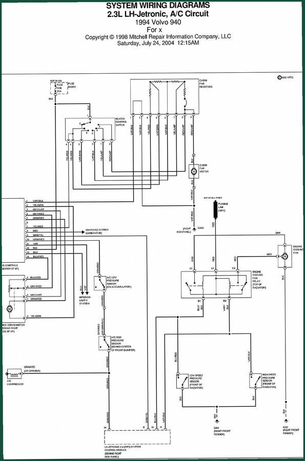
Volvo BM Michigan 940 2004 Wiring Diagram – Factory Electrical Schematics
Original price was: $13.09.$9.99Current price is: $9.99.
61-page factory wiring diagram for Volvo BM Michigan 940 (2004). Cooling fan circuit, power distribution, and ground points. OEM-original.
Description
Volvo BM Michigan 940 2004 Wiring Diagram
Ever spent an afternoon chasing a ground fault because the wire color on the aftermarket schematic didn’t match what was under the hood? That’s the exact reason you need the Volvo BM Michigan 940 2004 Wiring Diagram – the factory document straight from Volvo’s engineering vault. This is 61 pages of original circuits, terminal assignments, and splice locations. Not a reprint. Not a third-party summary. Real OEM data from 2004.
Cooling Fan Circuit: What the OEM Diagram Shows
On page 1 of this manual you get the cooling fan circuit laid out with Volvo’s own wire color codes – BLU/YEL, BLK, BLK/YEL, and the ground points G901 and G902. The aftermarket copies often simplify these into generic colors, but when you have a 940 with a fried fan relay, you need to know exactly which BLU/YEL feeds from the ignition switch and which one drops to the fuse/relay block. This diagram includes the full routing, including the splice at the right front fender. That level of detail saves you from cutting the wrong wire.
Why Factory Specs Beat Aftermarket Schematics
Aftermarket wiring diagrams are usually traced from a different year or model and then adjusted. They drop splices, merge grounds, and simplify connector pin counts. The factory Volvo BM Michigan 940 manual shows everything: the power distribution system with the 15A fuse, the relay block connections, and the ground stud locations. Each wire is identified by its stripe pattern. If the factory says the wire is BLU/YEL with a BLK tracer at splice S901, that’s what you’ll find. No guessing.
3 Circuits This Manual Covers
The 61 pages break down the 940’s electrical system into manageable sections. Three major circuits are fully documented:
– Cooling Fan Circuit (including the fan relay and thermal switch path)
– Power Distribution System (battery, alternator feed, main fuse block)
– Ignition Switch Circuit (HOT IN RUN, HOT AT ALL TIMES, and the starter solenoid path)
Each circuit includes the connector views and splice locations. For the full list, check the table of contents in the PDF.
Who Benefits from This 61-Page Wiring Diagram
If you own a Volvo BM Michigan 940 wheel loader or backhoe and need to fix an electrical gremlin, this is the document to have on your tablet. DIYers who want to install work lights or a radio without melting a harness will find the wire gauge and fuse ratings clearly marked. Shop owners who bill by the hour can’t afford to waste time on inaccurate schematics. This manual pays for itself on the first diagnosis.
Common Wiring Mistakes to Avoid
Don’t assume ground points are interchangeable. The 940 uses G901 on the right front fender and G902 on the left – they are not the same circuit. Using the wrong ground can cause voltage drop or even a fire. Also, never swap the BLU/YEL wire from the ignition switch with the BLU/YEL from the fan relay. They might be the same color, but one is switched power and the other is constant. The factory diagram shows the difference with a note about “HOT IN RUN” vs “HOT AT ALL TIMES”. Read those labels before you splice.
Related Manuals: Volvo 940 System Wiring Diagrams 1998 · Volvo C30 2007 Wiring Diagram · Volvo Trucks FH12 FH16 Wiring Diagram Service Manual
For a broader understanding of automotive wiring standards, see Automotive Wiring and the Automotive Industry Overview.
FAQ – Volvo BM Michigan 940 Wiring Diagram
- Does this wiring diagram cover the entire vehicle electrical system?
- It covers the major circuits: engine, charging, starting, lighting, and cooling fan. Optional accessories like auxiliary hydraulics or rear work lights are not included in this 61-page version.
- Is this a factory original document?
- Yes. The file is directly from Volvo’s technical publication system – 82911020177 – with the original 2004 layout and Volvo part numbers. Not a copy or aftermarket trace.
- Can I use this diagram to retrofit additional lights?
- You can, but you need to identify the correct splice points and fuse capacity. The diagram shows the existing circuits so you can tap into a switched +12V without overloading the harness. Read the fuse ratings on page 1 before adding any load.
- What format is the access?
- PDF. You can view it on a phone, tablet, or laptop. Print it for the workbench – the lines are clean and the wire colors are readable.
Stop chasing ghosts in your 940’s wiring. Access the Factory Manual and get the actual wire routing from Volvo – no shortcuts, no flattened diagrams, just the real OEM circuit data.
Additional information
| Brand | Volvo BM Michigan |
|---|---|
| Language | English |
4 reviews for Volvo BM Michigan 940 2004 Wiring Diagram – Factory Electrical Schematics
You may also like…
-
Sale!

Volvo BM Michigan A25F A30F Technical Manual – 24 Pages OEM Specs
Original price was: $40.50.$30.00Current price is: $30.00. -
Sale!

Volvo BM Michigan EC340, EC390 Technical Manual – 57 Pages Factory Spec
Original price was: $44.10.$30.00Current price is: $30.00. -
Sale!

Volvo BM Michigan FM9, FM12, FH12, FH16, NH12 2003 Service Manual – Factory Wiring Schematics
Original price was: $36.90.$30.00Current price is: $30.00. -
Sale!

Volvo BM Michigan VN, VHD 2003 Service Manual – 108 Pages | AutoFix Global
Original price was: $59.20.$37.00Current price is: $37.00.
Related products
-
Sale!

2006 Service Manual – International DT 466E, 530E Diesel Engine
Original price was: $67.50.$50.00Current price is: $50.00. -
Sale!

2011 Parts Catalog – International Truck OE Parts Documentation (1786 Pages)
Original price was: $34.50.$25.00Current price is: $25.00. -
Sale!

1991 Electrical Schematic – 112-Page OEM Wiring Diagram for International 1000-3000 Series
Original price was: $22.75.$17.50Current price is: $17.50. -
Sale!
1994 Troubleshooting Manual – International 1000-4000 FBC
Original price was: $60.00.$50.00Current price is: $50.00.
Michael T. –
This is exactly what I required. The file is high resolution. A must-have for any Volvo BM Michigan BM mechanic doing maintenance. Saves me hundreds of dollars.
Robert M. –
This is exactly what I was looking for. The document is high resolution. Contains precise wiring diagrams for Volvo BM Michigan. Saved my repair job! Thanks.
Thomas B. –
This is just what I was looking for. The PDF quality is excellent. A must-have for any Volvo BM Michigan BM DIYer doing repairs. I will recommend this shop to others.
workshop_guy –
Perfect factory service manual. The pages are clean and easy to navigate. Contains precise bolt torque specs for Volvo BM Michigan. Saves me hundreds of dollars.