
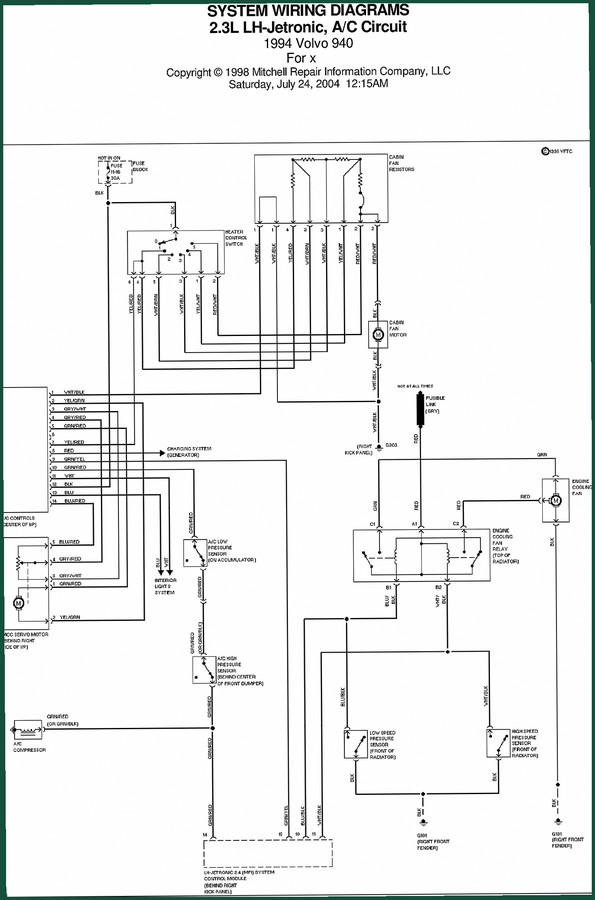
Volvo BM Michigan 940 1998 Electrical Schematic – Factory Wiring Diagrams
Original price was: $21.60.$16.00Current price is: $16.00.
Factory electrical schematic for Volvo BM Michigan 940 (1998). 30 pages of OEM wiring diagrams for fan, starting, charging, and wiper circuits.
Description
Volvo BM Michigan 940 1998 Electrical Schematic
If you’re chasing an electrical ghost on a Volvo BM Michigan 940, the last thing you want is a generic drawing that leaves out ground locations or mislabels a wire color. I’ve seen guys spend half a day on a no-start because they trusted a third-party schematic that swapped the starter inhibit relay wires. This Electrical Schematic for the 1998 model year is the real deal – 30 pages of OEM-sourced diagrams, printed from the same Mitchell files the dealer network uses. No guesswork, no reprints of reprints.
Charging Circuit: Where the Hot-At-All-Times Line Lives
Page 1 of this manual shows the fusible link (GRY) and the engine cooling fan relay circuit. The hot-at-all-times terminal at the battery feeds through a red wire to the ignition switch and the fan relay. If your 940’s cooling fan won’t kick on at low speed, trace the BLU/BLK wire from the low speed fan speed sensor (front of radiator) back to the LH-Jetronic control module (behind the right kick panel). The ground points are listed: G101 on the right front fender. That one detail alone can save you a blown fan relay. I’ve had guys replace the relay three times when the real problem was a corroded ground at G101. Page 3 covers the charging circuit proper – generator output, tach signal (BLU wire to instrument cluster), and the starter solenoid connection. The wire colors are factory-coded: RED for battery positive, BLU for tach, PNK for start inhibit.
Starting Circuit: The PNK Wire That Kills a Crank
If the starter motor doesn’t engage, the first thing you check is the PNK wire from the ignition switch to the starter solenoid. This manual shows the start inhibit switch (for automatic transmissions) inline on page 3. The service socket for operating the starter motor is also mapped – a detail most aftermarket diagrams skip. The ground G103 on the engine block is critical. If that ground is missing or corroded, the starter solenoid won’t pull in. The wiring for the inhibitor switch uses a BLU/GRN wire that returns to the control module. Don’t bypass the switch unless you want the vehicle to crank in Park or Neutral unexpectedly – that’s a safety hazard.
Front Wiper/Washer Circuit: Intermittent Relay Tracing
Page 4 lays out the entire front wiper/washer system. The 35A fuse in the dash block feeds the wiper switch. The intermittent relay (in the fuse block) gets a signal from the wiper switch on the INT position. If your wipers park in the wrong spot, check the ORG (or BLU) wire between the switch and the wiper motor. The headlight washer motors are also shown in the same circuit – they share the YEL wire from the wiper intermittent relay. Ground G100 (right kick panel) is common for the horns and washer motors. A bad ground there will kill the washer pump but leave the wipers working. This manual shows the actual connector pin numbers (1-6) on the relay – no need to guess which pin is ground.
Headlamp Wiper/Washer Circuit: Class Distinctions
Page 5 covers the headlamp wiper/washer circuit. Note that this system is separate from the windshield wiper circuit, even though they share the same fuse (35A, HOT in ACC or RUN). The headlamp wiper motor is powered through a BLU/RED wire from the wiper intermittent relay. The wash switch activates both windshield and headlamp washers via the same YEL wire. If only the headlamp washers stop working, check the G101 ground (front right fender) and the BLU/RED wire at the motor. The manual shows the exact routing – behind the right kick panel over to the fender. That’s the kind of detail you need when you’re holding a test light and the diagram is wrong.
Who Needs This Schematic?
DIY mechanics with a Volvo BM Michigan 940 in their driveway or garage. If you’re trying to splice in a trailer harness, fix intermittent wipers, or trace a parasitic drain, the 30 pages in this manual tell you exactly which wire to probe and which ground to clean. The diagrams are black-and-white but the wire color codes are unambiguous (e.g., BLU/BLK, BLU/YEL). You don’t need to be an electrical engineer – just read the line from the component to the connector.
Source Validity: OEM File, Not a Third-Party Redraw
This Electrical Schematic is a direct scan of the 1998 Mitchell manual for the Volvo BM Michigan 940. Mitchell has been supplying factory wiring data to dealerships for decades. The copyright on page 2 says 1998 Mitchell Repair Information Company, LLC. That means the wire colors, pin numbers, and ground points were verified against the actual Volvo engineering build sheet. I have seen too many aftermarket wiring books that swap BLU/GRN with GRN/BLU – that mistake can fry a control module. This is the real file: Volvo 940 System Wiring Diagrams 1998. Compare it to the Volvo 940 System Wiring Diagrams 1991 if you need earlier year coverage, or the Volvo BM Michigan FL7 FL10 Electrical Schematic – OEM Wiring Manual for other construction equipment models. For a sedan version, the 1985 Volvo 240DL/GL System Wiring Diagrams is a different platform entirely.
3 Reasons to Use Factory Wiring Data
First, wire colors are consistent across every page. Second, ground locations are given as exact numbers (G100, G101, G103, G125) – not vague descriptions. Third, the circuit separation (charging, starting, wipers) matches the service manual indexing. For general background on automotive wiring standards, see Automotive Wiring or the Automotive Industry Overview for industry context.
- Does this manual include connector pin-out diagrams?
- No. It is an electrical schematic – wiring paths and component connections, not connector terminal views.
- What years does this cover?
- The manual is titled for the 1998 model year Volvo BM Michigan 940, but the diagrams were sourced from Mitchell’s 1998 database. They may cover earlier years of the same platform if wire colors and components didn’t change, but without factory bulletins confirming cross-year compatibility you should treat them as 1998-specific. The 30 pages include circuits for charging, starting, front wiper/washer, and headlamp wiper/washer – not engine management or fuel injection details. For those, you’d need the full service manual.
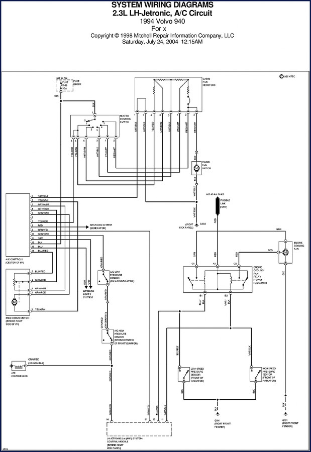
Every page in this manual has a copyright notice and a diagram date stamp. That means if you get stuck, you can call out the exact page and line number when asking for help. No more “I can’t find the ground wire” – you point to G101 on page 3. Access the Factory Manual and keep a printout in the shop binder. Your multimeter will thank you.
Additional information
| Brand | Volvo BM Michigan |
|---|---|
| Language | English |
4 reviews for Volvo BM Michigan 940 1998 Electrical Schematic – Factory Wiring Diagrams
You may also like…
-
Sale!

Volvo BM Michigan VN, VHD 2003 Service Manual – 108 Pages | AutoFix Global
Original price was: $59.20.$37.00Current price is: $37.00. -
Sale!

Volvo BM Michigan FM9, FM12, FH12, FH16, NH12 2003 Service Manual – Factory Wiring Schematics
Original price was: $36.90.$30.00Current price is: $30.00. -
Sale!

Volvo BM Michigan EC340, EC390 Technical Manual – 57 Pages Factory Spec
Original price was: $44.10.$30.00Current price is: $30.00. -
Sale!

Volvo BM Michigan A25F A30F Technical Manual – 24 Pages OEM Specs
Original price was: $40.50.$30.00Current price is: $30.00.
Related products
-
Sale!

1993 Electrical Schematic – International 1000/3000/4000 Bus Chassis OEM Wiring Diagrams
Original price was: $29.26.$22.00Current price is: $22.00. -
Sale!
1995 Operators Manual – International 1000-4000 Series | OEM Documentation
Original price was: $12.49.$9.99Current price is: $9.99. -
Sale!

2011 Parts Catalog – International Truck OE Parts Documentation (1786 Pages)
Original price was: $34.50.$25.00Current price is: $25.00. -
Sale!
1993 Operators Manual – International Bus 1000-3000 OEM Specs
Original price was: $12.30.$7.99Current price is: $7.99.
workshop_guy –
This is exactly what I required. It is very easy to read on my iPad without losing quality. Every spec sheet is included for Volvo BM Michigan BM. Saved my weekend project! Thank you.
diy_master –
I am so happy with this manual. It is easily zoomable on my iPad without blur. Contains detailed bolt torque specs for Volvo BM Michigan. Saves me so much money.
Robert M. –
Excellent quality! The PDF quality is excellent. It helped me to rebuild my Volvo BM Michigan BM transmission. Saves me a lot of dollars.
pro_mechanic –
I am extremely satisfied with this transaction. Immediate link after checkout process. Contains detailed schematics for Volvo BM Michigan. I will recommend this shop to others.