
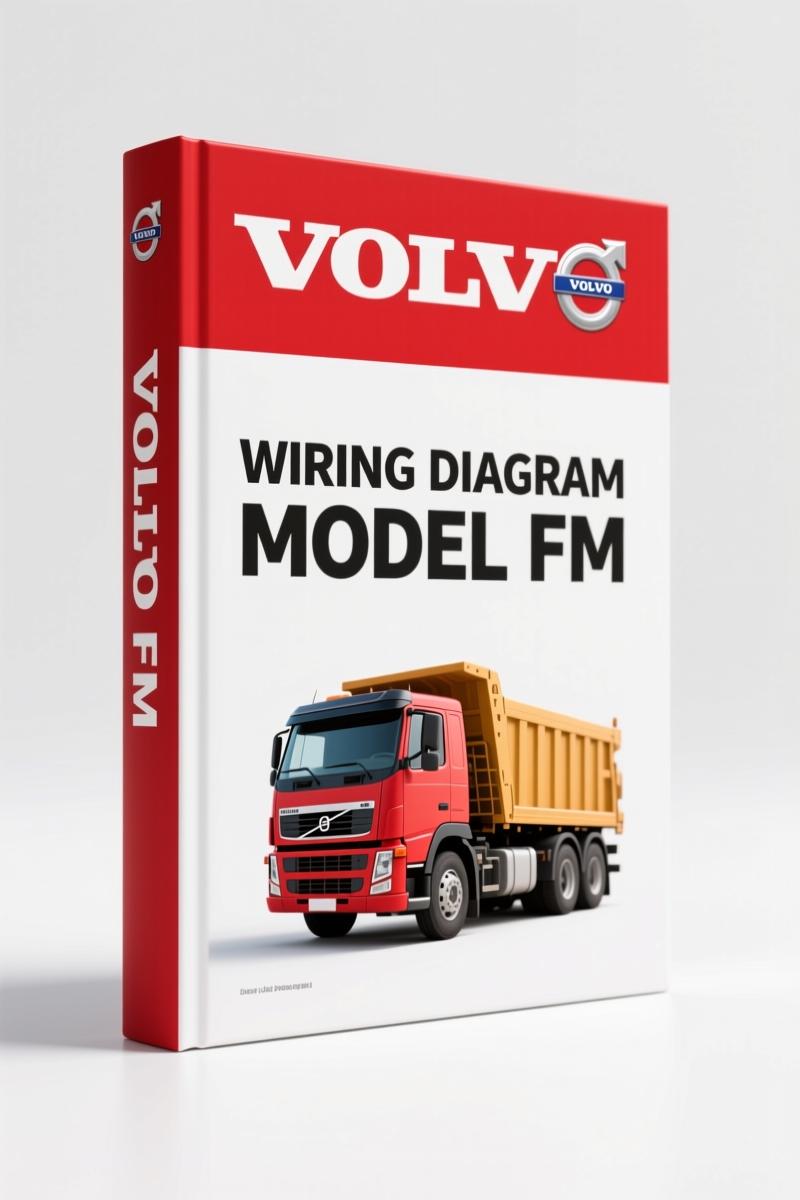
Volvo BM FH, FM Wiring Diagram – 242-Page Factory Electrical Schematics
Original price was: $35.00.$25.00Current price is: $25.00.
OEM Volvo BM FH, FM wiring diagram manual – 242 pages of factory electrical schematics, ground connections, and component indexes.
Description
Volvo BM FH, FM Wiring Diagram – Factory Specs for Electrical Diagnosis
You’ve got a Volvo BM FH, FM Wiring Diagram problem on your hands – a no-start, a blown fuse you can’t trace, or a MID code that points to a module buried somewhere in the chassis. Without the OEM wiring diagram, you’re guessing. Guessing costs you billable hours and sometimes a control unit that wasn’t even bad. I’ve seen guys replace three ECUs before they cracked the manual. Don’t be that guy.
This is the factory wiring diagram for Volvo BM FH and FM trucks. 242 pages of what Volvo themselves use on the assembly line. Not a third-party redraw. Not a generic schematic. The same document that Volvo Truck Corporation printed in Göteborg. That’s your shortcut to a fix that sticks.
Electrical System Coverage: 242 Pages of Factory Wiring
The manual opens with an example of a wiring diagram – page 2 tells you how to read the symbols and the safety warnings. Note: the foreword from September 07 makes it clear that Volvo issues service bulletins when specs change. That’s why you want the original print, not a copy someone scanned three times. The table of contents lists every section you need: Component wiring diagram index, Component wiring diagrams, Illustrations, Fuses (page 209), Relays (page 211), Wiring harness illustration index, Ground connections, List of ground connections, List of connectors, List of components, Abbreviations, Cable colour code. You get the full index from page 3 onward.
That’s the difference between this and a cheap aftermarket PDF. You need the charge pressure at a given pin? You go to the component wiring diagram section. Need to find which connector is J2? Look up the list of connectors. It’s all cross-indexed by component number and MID number in the illustrations section.
What’s Inside the Wiring Diagram Index?
The component wiring diagram index (page 5) gives you a map to every subsystem. Engine, transmission, ABS, body electronics, trailer interface. Each diagram is a full-page layout with colour-coded wires – the cable colour code abbreviation list is included so you know what HB, GN, BN mean. The illustrations section (starts page 112) shows physical locations of connectors, ground points, and relays. If you’ve got a circuit that drops voltage when you wiggle the harness, that’s where you start.
Take the ground connections list (page 218). It tells you exactly where each ground is bolted to the chassis. On a Volvo FM, a bad ground at G30 can cause the entire dash cluster to flicker. Without this list, you’re chasing ghosts.
Fuses, Relays, and Ground Connections: Why Factory Specs Matter
Page 209 is the fuse layout. Not a generic table – factory amperage ratings, circuit numbers, and the exact cavity each fuse goes into. Relays start on page 211 with pin assignments. If you’ve ever swapped a relay only to find the coil polarity was backwards on a non-OEM part, you know why this matters. The wiring harness illustration index (page 213) shows how the harnesses route through the cab and frame. That alone saves you from cutting into the wrong bundle.
For a professional tech, the cross-index of component number to MID number (illustrations section) is gold. You get a fault code like MID 144? Flip to the cross index, find the component, jump to its wiring diagram. That’s the kind of workflow you can’t get from a Chilton or a Haynes. Those books assume one-size-fits-all. This manual assumes you have a specific truck with a specific CHID range – A652195-, B486535-, E735697-, CKD875563- for this edition.
Does This Manual Include Component Location Data?
It does. The illustrations section (starting page 112) shows the physical layout of every electrical component. You get connector face views with pin numbers. If you need to backprobe a control unit, you can see the exact cavity orientation. That’s what lets you test without shorting two pins together. The list of connectors (page 219) gives you the connector type, number of pins, and colour. Combined with the ground connection list, you can trace a circuit end-to-end without looking at the truck.
One thing I appreciate: the cable colour code abbreviations. You don’t have to interpret a blurry scan – every wire colour is spelled out in a table. SB = SB (sky blue), GN = green, etc. When you’re working on a 24V system, one misread wire can fry a module. Having the factory legend removes that risk.
Verify Your Source: OEM vs Aftermarket Wiring Diagrams
I’ve been burned by aftermarket wiring diagrams. They leave out grounds, show the wrong pinout, or simplify circuits so they barely work for basic troubleshooting. This is the real thing – Volvo BM OEM documentation, order number 20177893. If you need a companion service manual, check the VOLVO FH Wiring Diagram Service Manual. For brake circuit schematics, the Volvo FH FM Pneumatic Brake Circuit Diagram covers air systems. And if you only need the FM chassis, there’s a separate Volvo FM Wiring Diagram.
For more on how to read automotive wiring diagrams in general, the Automotive Wiring resource from Wikipedia covers colour coding standards, and Automotive Wiring from SAE International explains terminal numbering. But you don’t need a textbook when you have the factory diagram in front of you.
- Does this wiring diagram cover all FH and FM models?
- It covers FM and FH Version 2 trucks built after certain VIN breakpoints listed on page 1. Earlier trucks may differ. Check your CHID against the ranges in the manual.
- Can I use this to diagnose a no-start condition?
- Yes. Start with the component wiring diagram index to find the engine management circuit, then trace power and ground from the battery to the ECM, fuel pump relay, and ignition. The fuses and relays sections show you exactly what circuit each fuse protects.
- Are the connectors labelled with part numbers?
- The list of connectors gives you connector type and number of pins, but not always the OEM part number itself. You may need a complementary parts catalog for that. The manual focuses on electrical function and location.
- What if I find an error in my manual – does Volvo issue corrections?
- The foreword states that service bulletins are issued when product updates affect the manual. This edition is dated September 07. If your truck is newer, supplement with Volvo service bulletins for sure.
If you want to stop wasting time with aftermarket schematics that leave out the ground points and connector pinouts, this is the solution. 242 pages of factory data, indexed and cross-referenced the way Volvo intended. Access the Factory Manual and get back to fixing trucks, not guessing.
Additional information
| Brand | Volvo BM |
|---|---|
| Language | English |
2 reviews for Volvo BM FH, FM Wiring Diagram – 242-Page Factory Electrical Schematics
You may also like…
-
Sale!

Volvo BM 4600 1984 Parts Catalog – OEM Factory Parts Identification
Original price was: $70.20.$45.00Current price is: $45.00. -
Sale!
Volvo BM L120D Service Manual – 603 Pages Factory OEM Documentation
Original price was: $64.35.$45.00Current price is: $45.00. -
Sale!
Volvo BM P1800 Service Manual – 220 Pages Factory OEM Specs
Original price was: $49.60.$40.00Current price is: $40.00. -
Sale!

Volvo BM VN, VHD Service Manual – 104 Pages Factory Preventive Maintenance
Original price was: $60.80.$40.00Current price is: $40.00.
Related products
-
Sale!

2004 Acura TSX Wiring Diagram – 73-Page Factory Electrical Schematics
Original price was: $15.88.$9.99Current price is: $9.99. -
Sale!

1995 Operators Manual – International 1000-4000 Series | OEM Documentation
Original price was: $12.49.$9.99Current price is: $9.99. -
Sale!
1994 Troubleshooting Manual – International 1000-4000 FBC
Original price was: $60.00.$50.00Current price is: $50.00. -
Sale!
1992 Electrical Schematic – OEM Wiring Diagrams for International 1000-3800
Original price was: $24.48.$18.00Current price is: $18.00.
workshop_guy –
I am extremely satisfied with this manual. The text is searchable and easy to navigate. A must-have for any Volvo BM BM mechanic doing maintenance. Saves me hundreds of dollars.
Michael T. –
This is just what I required. Instant access after payment. It assisted me to fix my Volvo BM BM engine. Saves me so much dollars.