
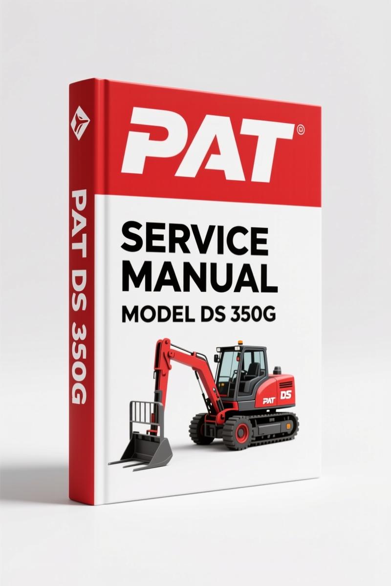
PAT DS 350G, DS 350GW 2001 Service Manual – OEM LMI Diagnostics
Original price was: $59.40.$45.00Current price is: $45.00.
OEM service manual for PAT DS 350G/GW LMI. 64 pages covering electrical diagrams, theory, and troubleshooting flow charts.
Description
PAT DS 350G, DS 350GW 2001 Service Manual – Factory Specs for Load Moment Indicator
You’ve got a DS 350G on the pad throwing a load reading error, and the foreman’s tapping his watch. Don’t reach for a generic PDF farm. This is the OEM PAT DS 350G, DS 350GW 2001 Service Manual – 64 pages of factory data, not aftermarket junk. PAT America, Inc. put this together for their hydraulic boom crane LMI system, Rev B, dated 04/18/01. It’s the same binder their techs used when a DS 350GW came in with a dead display.
If you’ve ever wasted half a shift chasing a bad ground because some third-party manual left out the pinouts, you know the difference. This one gives you the Electrical diagrams, mechanical descriptions of every component, and the theory behind the six measuring channels. It also includes a full set of troubleshooting flow charts that cover no display, anti-two-block malfunctions, length reading errors, load reading problems, and interference issues. That’s not fluff – that’s the difference between a two-hour fix and a two-day headache.
PAT DS 350G, DS 350GW 2001 Service Manual: Mechanical and Electrical Description
Section 1 dives into the mechanical description of the components – cable reel, length sensor, angle sensors, anti-two-block switch, pressure transducer. It also covers the central unit’s hardware and basic adjustments. You get part numbers like 068-208-060-013 for the cable reel and 006-710-006-002 for the length sensor. That’s OEM catalog data you can order from directly, not a vague “use standard sensor.”
Section 2 defines the terms used in the manual – no guessing what “force transducer” means in this context. Section 3 has 20 drawings, from spare parts lists to full electrical diagrams. Page 13 walks you through EPROM replacement on the central unit board, including the exact pin locations and soldering tips. Page 11 gives you the pressure transducer cable assembly layout. These are the diagrams you trace when the console to central unit data line goes dead.
20 Electrical Diagrams for Sensor and Cable Reel Systems
Drawing 12 shows the central unit electrical diagram. Drawing 13 the cable reel. Drawing 14 through 16 cover A-frame, offset swingaway, and tele swingaway extensions. Drawings 17 and 18 detail the console-to-central-unit wiring – both versions. Drawing 19 is the cable reel to central unit, and Drawing 20 the pressure transducer to central unit. If your DS 350GW is showing bad data between the console and central unit, that flowchart on page 8 of the troubleshooting section points you straight to the wiring diagrams. No guesswork.
Every electrical diagram is labeled with signal names, connector pin numbers, and voltage ranges. You’ll find the zero-point adjustment procedure for the piston and rod pressure channels on Drawing 11 – that’s a common drift issue on these systems. PAT includes the procedure right there, not buried in an appendix.
Troubleshooting Flow Charts for Common Errors
The flow charts start with a general diagnostic tree, then branch into specific faults: no display, anti-two-block problem, length reading problem, load reading problem, bad data transfer between console and central unit, interference problem, and lightbar malfunction. Each chart asks the right questions – “Does the display show any segments?” – then tells you which section to hit next. This is the fast path when a rig is down and the rental clock is ticking.
Section 4, Theory, explains exactly how each measuring channel works. Theory 1 covers the anti-two-block and shutoff circuit – safety critical. Theory 2 through 7 break down length, piston pressure, rod pressure, force transducer, main boom angle, and jib angle channels. You need that understanding to correctly interpret the error codes listed in Section 6. A generic manual won’t tell you that the rod side pressure channel (#3) has its own zero-point adjustment on the main board.
Check the Anti-Two Block Circuit Before You Lift
Drawing 6 shows the anti-two-block switch assembly, part number 031-002-060-011. The manual includes its mechanical description and the theory of operation. If that circuit is out of spec, your LMI won’t shut down the hoist when it should. PAT provides the voltage checks to verify the circuit at the central unit. You’ll find those in Theory 1 and the basic adjustment section. This is not a ‘maybe’ procedure – it’s a safety system.
Source Authenticity: PAT OEM vs Aftermarket Documentation
This manual came from PAT America, Inc., not a third-party reprint. The document number is 031-300-190-046, Rev B, dated 04/18/01. It includes the original copyright notice and revision history. Aftermarket manuals often omit the theory section or use generic electrical diagrams that don’t match your specific cable reel or sensor assembly. You need the exact adjustment values – the basic adjustment section specifies voltage checks that aftermarket sources ignore. If you’re working on a DS 350G or DS 350GW, this is the only source you should trust.
Related manuals:
PAT DS 350GM, RT875CC 2002 Service Manual – Load Moment Indicator
PAT DS150C, DS 150 2002 Service Manual – Factory Specs & Diagrams
PAT DS 350 IFLEX5 2003 Service Manual
If you need a deeper understanding of crane drivetrains, this manual does not cover Manual Transmission systems – it’s strictly the load moment indicator. For general transmission knowledge, Manual Transmission resources are separate.
- What torque specifications are included in this manual?
- None. This is a load moment indicator service manual, not an engine or drivetrain manual. It focuses on sensor adjustments, voltage checks, and electrical pinouts.
- Does this manual cover the DS 350G and DS 350GW models only?
- Yes. It is specifically for the PAT DS 350G and DS 350GW LMI systems on hydraulic boom cranes. It does not cover the DS 350GM, DS150C, or other models. Those are covered by separate service manuals. If you need the DS 350GM, see the related manual linked above. The 2001 version includes Rev B changes – text, error codes, and reference updates from the original 1998 troubleshooting manual. The 64 pages include all 20 drawings and 6 theory sections. If your crane uses a different cable reel part number, verify compatibility with your serial number.
Every shop that touches PAT DS 350G and DS 350GW systems should have this on the bench. It’s the difference between guessing and knowing. Access the Factory Manual from AutoRepairManuals and keep your load readings accurate and your lifts safe.
Additional information
| Brand | PAT |
|---|---|
| Language | English |
3 reviews for PAT DS 350G, DS 350GW 2001 Service Manual – OEM LMI Diagnostics
You may also like…
-
Sale!
PAT DS 160 2003 Technical Manual – Calibration Guide for LMI Systems
Original price was: $54.45.$45.00Current price is: $45.00. -
Sale!

PAT DS 150 2001 Operators Manual – OEM Load Moment Indicator
Original price was: $63.45.$45.00Current price is: $45.00. -
Sale!
PAT DS 350GM RT875CC 2002 Service Manual – OEM LMI Diagnostics
Original price was: $66.60.$45.00Current price is: $45.00. -
Sale!

PAT iFLEX5, DS 350 2003 Operators Manual – Factory Spec Data
Original price was: $68.85.$45.00Current price is: $45.00.
Related products
-
Sale!

2011 Parts Catalog – International Truck OE Parts Documentation (1786 Pages)
Original price was: $34.50.$25.00Current price is: $25.00. -
Sale!

Technical Manual – International DT 530 & HT 530 (118 Pages)
Original price was: $37.00.$25.00Current price is: $25.00. -
Sale!

1992 Electrical Schematic – International 1000/3000/4000/2554 OEM Wiring Diagrams (132 Pages)
Original price was: $26.40.$20.00Current price is: $20.00. -
Sale!

Technical Manual – International 6.0L Power Stroke FICM Diagnostics
Original price was: $29.80.$20.00Current price is: $20.00.
Michael T. –
This is just what I needed. Instant access after checkout process. It assisted me to repair my PAT DS engine. Saved my weekend project! Thanks.
James L. –
This is just what I needed. The scan is high-quality and well indexed. Every spec sheet is included for PAT DS. Saved my repair job! Thanks.
William H. –
Superb resource! The file looks clean. A must-have for any PAT DS DIYer doing repairs. I will recommend this shop to others.