
Officine Meccaniche TK140EA019AA00 2008 Wiring Diagram – Factory OEM Schematics
Original price was: $26.41.$19.00Current price is: $19.00.
Original 2008 wiring diagram for Officine Meccaniche TK140EA019AA00 – 20 pages of factory electrical schematics, colour codes, and PLC I/O maps.
Description
Officine Meccaniche TK140EA019AA00 2008 Wiring Diagram – OEM Factory Manual
Electrical troubleshooting on industrial equipment burns up billable hours faster than a shorted solenoid. You chase a ghost, swap a board, and it still won’t run. The issue is almost always the drawing. Aftermarket diagrams drop wire colors, skip PLC logic, or mix up terminal assignments. Officine Meccaniche TK140EA019AA00 2008 Wiring Diagram is the actual OEM print from the Italian factory — 20 pages of exactly what the engineer drew. No translation errors, no redrawn guesses. I’ve seen guys fry a $2,000 PLC because they used a generic diagram that showed +24 V on pin 5 when the factory had it on pin 6. Don’t be that guy.
What’s Inside This Wiring Diagram
Every sheet listed in the indice (page 2) is a specific subsystem. Cover sheet, revised sheets list, legend for symbols — all in Italian, English, and German. Then the meat: Diesel, Services, Emergency (page 6), Remote Control (page 7), PLC power supply (page 8), CPU digital input (page 9), I/O digital input (page 10), Analog input (page 11), CPU digital output (page 12), I/O digital output (page 13), I/O analog output (page 14). Two terminal block sheets (pages 15–16), Control panel (17), Inner layout (18), and the solenoid valves box (19). That’s your full electrical map.
Why the OEM Wiring Diagram Matters
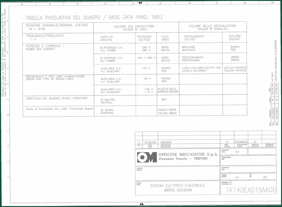
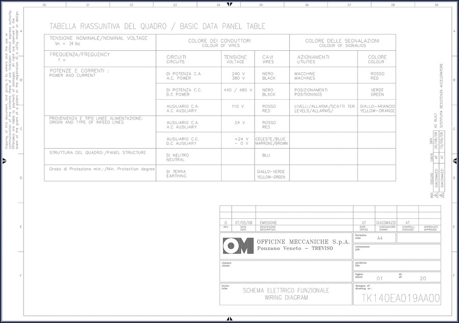
Aftermarket diagrams for industrial controls are a crap shoot. They often consolidate multiple variants onto one page and leave out the color-coding table. This factory print from Officine Meccaniche includes the exact colour of wires table from page 1: black for +24 V DC, blue for 0 V, red for 380 V AC power, yellow-green for earth. The legend on page 3 defines every symbol — pressure switch, diode, transducer, motor, connector, sensor, solenoid valve, battery, resistor, contact, generator, push-button. Without that key, you’re guessing which symbol means a normally open contact. The OEM version tells you.
3 Systems Where This Wiring Diagram Saves Your Back
1. Emergency circuit (page 6). This is the safety shutdown. Botch the wiring and the machine won’t stop when you hit the red button. The diagram shows exactly which contacts are NC, where the emergency relay coil is, and how it feeds the PLC. 2. PLC power supply (page 8). Wrong voltage rail? That’s a dead board. Page 8 gives the +24 Vdc and 0 V routing from the transformer to the CPU rack. 3. Solenoid valves box (page 19). These valves control hydraulic or pneumatic actuators. The diagram maps each solenoid to a specific digital output on the I/O board. Miswire one and the machine moves the wrong direction — grenades everything.
Using the Legend and Color Codes
Pull up page 3 before you touch a wire. The legend lists 15 symbols with triple-language labels. Match the symbol on the drawing to the actual component — for example, a circle with an ”M” is a DC motor, a rectangle with an ”F” is a fuse, a sine-wave symbol is a transducer. Page 1 has the colour of conductors table: black for DC power, blue for 0 V, red for AC auxiliary 380 V, yellow-green for earth. If you ignore these, you’ll reverse polarity on a sensor or land a live 380 V wire on a 24 V PLC input. I’ve seen the smoke. Use the legend.
Audience Fit: Who Needs This Manual?
Home garage enthusiasts who maintain industrial generators, water pumps, or conveyor systems — this wiring diagram is your path to a working machine. Professional techs who bill by the hour: stop wasting time calling the manufacturer’s support line. This 2008 diagram covers the TK140EA019AA00 control panel exactly. Beginners: read the legend first, then trace one circuit at a time. Don’t try to understand the whole drawing at once. Start with the emergency circuit on page 6, then the PLC power on page 8.
Automotive Wiring covers general wiring principles, and the Automotive Industry Overview gives context on how these diagrams evolved. For related manuals on commercial vehicle electrical systems, see Body Electrical Practice Electrical Wiring Diagrams, LDV Electrics 1 Vehicle Wiring 1994 Onwards RHD, and LDV Electrics 1 Vehicle Wiring Diagrams 1987-1992.
- Does this wiring diagram include torque specs?
- No. This is a wiring diagram, not a service manual. Torque values for bolts on the TK140EA019AA00 are in the factory service manual — not here.
- Can I use this for an Officine Meccaniche model built after 2008?
- The revised sheets list on page 2 shows the revision status of each sheet. If your machine’s serial number falls within the revision range listed, the diagram applies. For later models, Officine Meccaniche may have updated the PLC or added I/O boards. Always compare the revision date on the cover sheet (2008) to your equipment’s build date. If the panel looks different, order the newer diagram.
Access the Factory Manual. You get the original PDF — 20 pages of factory-drawn wiring, not a scan of a scan. Print it, laminate the legend page, and keep it in the panel cover. That’s what I do.
Additional information
| Brand | Officine Meccaniche |
|---|---|
| Language | English |
2 reviews for Officine Meccaniche TK140EA019AA00 2008 Wiring Diagram – Factory OEM Schematics
You may also like…
-
Sale!

2004 Acura TSX Wiring Diagram – 73-Page Factory Electrical Schematics
Original price was: $15.88.$9.99Current price is: $9.99. -
Sale!

Acura NSX 1991 Service Manual – 1420 Pages OEM
Original price was: $102.05.$65.00Current price is: $65.00. -
Sale!

CDS 705C, 706C, 708C 1981 Parts Catalog – OEM Forklift Specs
Original price was: $61.60.$40.00Current price is: $40.00. -
Sale!

Acura Integra 1998 Service Manual – 1891 Pages Factory OEM Documentation
Original price was: $31.75.$25.00Current price is: $25.00.
Related products
-
Sale!

1994 Troubleshooting Manual – International 1000-4000 FBC
Original price was: $60.00.$50.00Current price is: $50.00. -
Sale!
1992 Electrical Schematic – OEM Wiring Diagrams for International 1000-3800
Original price was: $24.48.$18.00Current price is: $18.00. -
Sale!

2011 Parts Catalog – International Truck OE Parts Documentation (1786 Pages)
Original price was: $34.50.$25.00Current price is: $25.00. -
Sale!
1995 Operators Manual – International 1000-4000 Series | OEM Documentation
Original price was: $12.49.$9.99Current price is: $9.99.
pro_mechanic –
This is just what I needed. Immediate link after payment. A must-have for any Officine Meccaniche Meccaniche mechanic doing repairs. Saves me so much dollars.
James L. –
Highly recommended! It is very easy to read on my phone without blur. A must-have for any Officine Meccaniche Meccaniche mechanic doing maintenance. Saved my repair job! Thanks.