
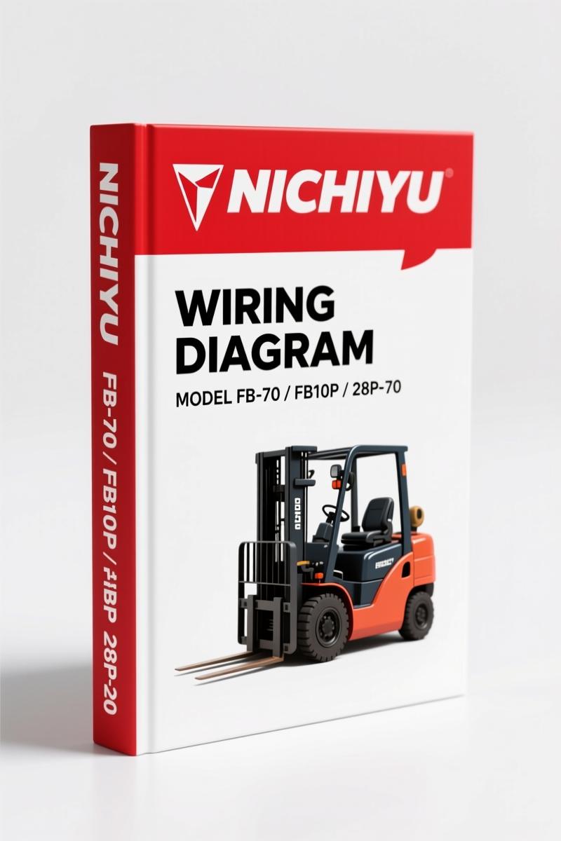
Nichiyu FB10P, FB30P, FB-70, 28P-70 Wiring Diagram – 23 Pages OEM
Original price was: $25.03.$17.50Current price is: $17.50.
OEM wiring diagram for Nichiyu FB10P, FB30P, FB-70, 28P-70. 23 pages of factory schematics, connector layouts, and wire color codes.
Description
Nichiyu FB10P, FB30P, FB-70, 28P-70 Wiring Diagram – No Aftermarket Guesswork
I have been turning wrenches for 28 years, and I have seen more fried controllers from guys using aftermarket wiring diagrams than I can count. If you are working on a Nichiyu FB10P, FB30P, FB-70, 28P-70 Wiring Diagram job, you need the factory document. This is 23 pages of OEM wire routing, connector pin numbers, and actual color codes – not some photocopy from a decrepit binder. The PDF starts with the 48V battery distribution (F1 100A, 420AF x4) and goes straight into the traction motor U, V, W phases with IGBT gate outputs. You get the exact pin assignments for line connectors PB101-05 through PB101-26, and the legend for harness mark colors (RD, BK, GN, YE, WH, BR, BU, GY, PK, OG). No guessing which stripe is which.
I have seen guys hook up a directional switch wrong because they trusted a third-party redraw. Then the forklift does a controlled spin right into a rack. This manual gives you the directional switch neutrality wiring and the hour meter countdown hookup. Broken lines? Optional equipment. Asterisk leads? Different diameters. It is all noted right there. Want to verify the lift rotary encoder or the tilt level potentiometer input? It is on the page. The EPS motor and controller circuit runs through PB101-20 to PB101-26. The display panel flat cable – 22P – is pinned out exactly. Mode select switch, reserved setting, switch GND – all there.
Traction Motor Phases and IGBT Gate Outputs
Each phase – U, V, W – lists gate outputs 0, 1, 2 and power supply (+/-) with specific wire codes like WHBK#, BWRD#, BKWH#, YBKE#, YE#, RD#, BKWH#. That matters when you are replacing an IGBT board and need to confirm the harness routing. The PDF shows the board-to-IGBT connections for both traction motor and hydraulic motor V and W phases. You also get the hydraulic motor U phase gate outputs. If you have ever chased a hydraulic pump relay that only works intermittently, this diagram will save you the multi-hour head-scratcher.
The charger panel section is only for trucks with built-in chargers, with separate F3 (15A) and F4 (10A) fuses after the key switch. The charger controller pinouts are in the same flow. This is the kind of detail that makes you trust a manual. No vague blocks labeled “connector A”.
Wiring Harness Color Codes and Connector Pin Numbers
The reference table at the bottom of page 1 (and continued throughout) gives you every two-letter color abbreviation and the example BKWH (Black/White) with a diagram showing how the white line runs on the black wire. That sounds basic, but you would be surprised how many aftermarket diagrams skip the stripe orientation. I have had apprentice techs swap RDWH for WHRD and wonder why the controller throws a code. This manual gives you the exact order of colors in the stripe notation.
For each line connector (PB101-20 to PB101-26) the manual lists the pin number, the wire color pair, and where it goes. For instance, PB101-21 includes YEBK, BNBK, RDGW, RDWH. If you are diagnosing an EPS sensor fault, you trace from the sensor to the EPS controller to that connector. It is all in the same 23 pages.
Does This Manual Cover the FB-70 System Wiring?
Yes. The OCR excerpt shows a section titled “FB-70 System wiring” and then a subsection “FB10P – 28P-70”. That means this single PDF bundles the wiring for the FB-70, FB10P, and 28P-70 models. If you have an FB30P, the same wiring architecture applies – note the model number in the file name includes “FB30P”. The 23 pages cover the 48V battery distribution, traction and hydraulic motor IGBT stages, EPS motor, directional switch, display, and charger options. You also get the auxiliary A/D output wiring for load sensing attachments.
I have used this type of factory diagram to trace a no-forward fault on an FB-70 that turned out to be a corroded pin on PB101-25 (RDYE/BUYE/WHGN/BNBK). Without the OEM pinout, I would have been swapping controllers. Do that.
3 Reasons to Use Factory Nichiyu Wiring Documentation
First: aftermarket diagrams combine different model years and assume pin compatibility. This manual is specific to the FB10P, FB30P, FB-70, and 28P-70. Second: the fuse and circuit protector ratings (100V 420AF, 15A, 10A) are printed next to the components – you do not have to guess if the key switch F4 is a 10A. Third: the optional equipment is called out with broken lines. If your truck has a built-in charger, you see the separate charger controller and its connector. If not, those wires are not present. That reality check saves you from chasing phantom circuits. For additional troubleshooting help, check the NICHIYU FB Series Troubleshooting Manual and the NICHIYU FB-DC70 Series Troubleshooting Manual for diagnostic flowcharts. The Nichiyu FB-DC70 Series Workshop Manual covers mechanical disassembly if you need to get to the wiring physically. Outside the forklift world, a solid grounding in Automotive Wiring principles helps understand why Nichiyu uses twisted pairs for the gate signals. For industry context, the Automotive Industry Overview on factory documentation standards applies here.
FAQ – What You Are Really Asking
- What models does this 23-page wiring diagram cover?
- It covers Nichiyu FB10P, FB30P, FB-70, and 28P-70. The file name includes all four. The internal sections reference FB-70 system wiring and FB10P-28P-70 specifically.
- Are the wire colors in the manual actual OEM colors or generic red/black?
- OEM colors with two-letter codes and stripe notation. Red=RD, Black=BK, Green=GN, Yellow=YE, White=WH, Brown=BR, Blue=BU, Gray=GY, Pink=PK, Orange=OG. The manual shows harness mark/color pairs like BKWH (Black/White) with a diagram indicating which side has the stripe.
- Does this include the EPS (electric power steering) wiring?
- Yes. The EPS motor, EPS controller, and EPS sensor are all shown with their connections to line connectors PB101-20 through PB101-26. The EPS sensor wiring is particularly useful because failure often sets a false speed signal.
- I have an FB30P without a built-in charger – will the charger section confuse me?
- No. The manual marks optional equipment with broken lines. The charger panel and charger controller sections are labeled “Only for trucks with built-in chargers.” If your truck does not have it, ignore those broken-line branches. The rest of the wiring remains the same.
Look, I have been through enough exploded harnesses to know that the difference between a three-hour job and a three-day job is the right diagram. This Nichiyu factory wiring manual gives you the exact IGBT gate sequences, connector pin numbers, and wire stripe orientation that the engineers put on the drawing board. Do not trust a scan from a forum. Get the original 23-page PDF. Access the Factory Manual and keep it on your tablet next to the lift truck. Your multimeter will thank you.
Additional information
| Brand | Nichiyu |
|---|---|
| Language | English |
2 reviews for Nichiyu FB10P, FB30P, FB-70, 28P-70 Wiring Diagram – 23 Pages OEM
You may also like…
-
Sale!
Nichiyu FBR-75 2008 Troubleshooting Manual – OEM Diagnostic Data
Original price was: $58.05.$45.00Current price is: $45.00. -
Sale!
Nichiyu FB10P, FB30P Workshop Manual | 97 Pages OEM
Original price was: $67.50.$45.00Current price is: $45.00. -
Sale!
Nichiyu FBT13P, FBT15P, FBT18P, FBT20PN Service Manual – 154 Pages of Factory Specs
Original price was: $52.00.$40.00Current price is: $40.00. -
Sale!
Nichiyu FBT13P, FBT15P, FBT18P, FBT20PN Troubleshooting Manual – 105 Pages of Factory Diagnostic Data
Original price was: $54.45.$45.00Current price is: $45.00.
Related products
-
Sale!

Hangzhou Forklift Truck CPCD30/35N-RW15A Parts Catalog – 376 Pages OEM
Original price was: $25.00.$20.00Current price is: $20.00. -
Sale!

Baoli CPCD 80, CPCD 100 Service Manual – 112 Pages OEM Factory Specs
Original price was: $44.48.$32.00Current price is: $32.00. -
Sale!

Baoli 5-7 Ton Forklift Service Manual – Official Factory Specs
Original price was: $29.00.$20.00Current price is: $20.00. -
Sale!

E-P Equipment CPQD15/18N-RW21-Y, CPQD20/25/30/35N-RW22-Y 2008 Service Manual
Original price was: $44.70.$30.00Current price is: $30.00.
William H. –
Superb resource! It is easily zoomable on my tablet without losing quality. A must-have for any Nichiyu FB10P, owner doing maintenance. Highly recommended for mechanics.
diy_master –
Great OEM spec sheet. The pages are clean and well indexed. A must-have for any Nichiyu FB10P, DIYer doing repairs. Worth every penny.