
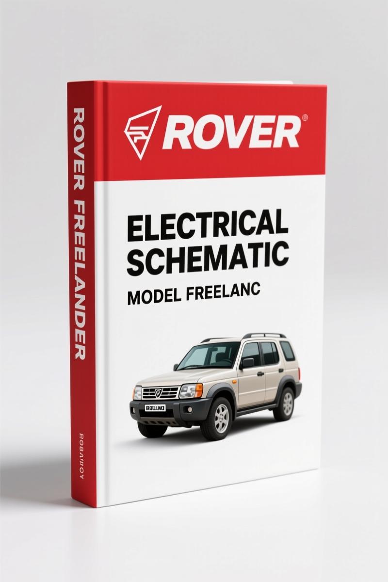
Land-rover Freelander 1996 Electrical Schematic – Factory OEM Wiring
Original price was: $15.98.$9.99Current price is: $9.99.
Factory 1996 Freelander electrical schematic – 73 pages of OEM wiring diagrams, colour codes, splice tables. For diagnostics and repair.
Description
Land-rover Freelander 1996 Electrical Schematic
I’ve seen more than a few guys pull their hair out chasing electrical ghosts on a Freelander. You grab a generic wiring diagram off the internet, and next thing you know you’ve got a blown fusebox, or worse, a fried ECU. That’s why this Land-rover Freelander 1996 Electrical Schematic exists. It’s the exact same folder Rover Group Limited put on the dealer bench in ’96. 73 pages of OEM circuit diagrams, colour codes, and header joint tables – not some aftermarket re-draw. If you’re working on the charging system, ABS, or the Central Control Unit, you want the factory route, not a guess.
You get Power Distribution first – the whole path from battery to both engine and passenger compartment fuseboxes, including the internal circuitry inside those boxes. Then Earth Distribution, split RHD and LHD. That’s page 3 in the original folder. And before you touch a wire, you need the COLOUR CODES table on page 2: B for Black, G for Green, K for Pink, LG for Light Green – twelve codes that never change across the entire harness. I’ve had guys tell me they “remembered” a wire colour and cooked a sensor. Don’t be that guy.
Power Distribution and Earth Distribution Coverage
The schematic organizes everything like a proper factory manual: Power distribution diagram shows battery-to-fusebox connections, followed by Headers and Splices tables. Those tables list each splice by number (e.g., A82) and give the wire gauge in square millimetres – imperial equivalent is roughly 16 AWG to 14 AWG depending on the circuit. Earth distribution uses the same header/splice method. If a tail lamp isn’t grounding, check the associated splice joints first. That approach narrows your search area fast. You don’t chase half the harness; you check the splice table and go straight to the joint.
What Systems Are Covered in This Schematic?
Everything electrical in a 1996 Freelander. I’ll list the big ones: Engine Management – MEMS for K‑Series, EDC for L‑Series diesel. ABS (Anti‑lock Braking System) with its own circuit. SRS (airbags), Charging and Starting, Central Control Unit, Anti‑theft Alarm and Central Door Locking, Windows, Sunroof, Door Mirrors, Cooling Fan (K and L series), Heater, Air Conditioning, Wipers, Exterior and Interior Lamps, Instruments, Horn, Cigar Lighter, Accessory Socket, and In‑Car Entertainment. Each system gets its own page with a clean schematic, no cross‑hatching. The Automotive Wiring standards used here are the same as any British Leyland era – trust the colour codes.
Use the Colour Codes Correctly
Page 2 has the full colour code table. Wire attributes also show the cross‑section area and, in Power/Earth sections, the wire length in millimetres. That length data lets you locate internal splices – look for the shortest wire between joint and connector. For example, the manual shows C574‑4 is 150mm from joint A82. That kind of precision saves you from cutting open the harness looking for a break that isn’t there. I’ve used that trick on a K‑Series no‑start with a hidden splice corrosion.
ABS Diagnostics: Factory Wiring Route
The ABS circuit diagram is separate – no mixing with engine or CCU lines. You trace the power feed from the fusebox, through the ABS relay, to the modulator. Earth returns are on a dedicated ground point. If you get an intermittent ABS light, the factory route helps you check the wheel‑speed sensor wiring at the splice joints. Generic diagrams combine circuits; this one keeps them isolated. That’s the difference between one hour and three hours of diagnosis.
73 Pages of OEM Wiring Data
Every page is a scan of the original 1996 binder – no reprints, no aftermarket edits. The header joints and splice tables are exactly as Rover printed them. You get separate RHD and LHD diagrams for earths, alarms, lamps, and wipers. That matters if you’re working on a left‑hook import with a different tail door layout. The Automotive Industry back then didn’t share schematics across markets; this manual keeps them separate.
Related Manuals
- Land Rover Freelander Owner’s Guide Softback Hardback
- Land-rover 75 Electrical Schematic – Factory Wiring Manual
- Rover DEFENDER 90/110/130 1997 Electrical Library
Who Should Use This Manual?
Home garage guys who own a 1996 Freelander and want to fix their own wiring without burning down the car. Beginners who can read a schematic but need the actual factory colours. Professional mechanics who bill by the hour and can’t afford to guess which wire feeds the CCU. If you can handle a multimeter and a soldering iron, this manual turns a frustrating electrical problem into a trace‑and‑fix job. Don’t expect a repair guide – this is purely the electrical schematic, so you still need the service manual for component R&R. But for the wiring, it’s the single source you should rely on.
Source Authenticity – OEM vs Aftermarket
Aftermarket electrical schematics are notorious for swapping wire colours or omitting splices. I’ve seen a “universal” Freelander diagram that used green for ground – original is black. That mistake can smoke a sensor. This manual is the original Rover Group Limited 1996 publication. The PDF is a direct scan from the factory binder. The page numbers are original, the header joints are original. If you’ve ever tried to fix a CCU lockout with a third‑party print, you know the pain. Don’t repeat it.
- Does this manual cover the 1.8 K‑Series engine management wiring?
- Yes, the MEMS section covers the K‑Series engine management system completely, including the injector and ignition coil circuits.
- I’m a beginner – will I understand the diagrams?
- The diagrams use standard automotive schematic symbols, and the manual includes a “How to Use the Circuit Diagrams” section (page 3) that explains the power/earth flow, header tables, and wire attributes. If you can read a street map, you can follow these diagrams. Start with the Power Distribution to understand how 12V gets to the fuseboxes, then pick one system like the cooling fan. Each circuit is self‑contained. That said, you should have a basic multimeter and know how to test for continuity. The manual won’t teach you electronics – it gives you the roadmap.
You need the factory wiring to keep that Freelander on the road. Access the Factory Manual now – it’s the exact 73-page OEM schematic that Rover dealers used. No aftermarket shortcuts, no colour code confusion. Just the original 1996 electrical library.
Automotive Wiring and Automotive Industry Overview provide broader context, but for the Freelander, this is your only wiring reference.
Additional information
| Brand | Land-rover |
|---|---|
| Language | English |
3 reviews for Land-rover Freelander 1996 Electrical Schematic – Factory OEM Wiring
You may also like…
-
Sale!
Land-rover 214, 414 1997 Service Manual – OEM Factory Specs
Original price was: $33.50.$25.00Current price is: $25.00. -
Sale!
Land-rover 101 Repair Manual – Factory MoD Specs for 1 Tonne 4×4
Original price was: $66.60.$45.00Current price is: $45.00. -
Sale!
Land-rover 25, 45, 220, 420, 620 1999 Repair Manual – Factory Specifications
Original price was: $37.80.$30.00Current price is: $30.00. -
Sale!
Land-rover 200, 114, 214, 414, 216 2001 Repair Manual – Factory Specs
Original price was: $44.70.$30.00Current price is: $30.00.
Related products
-
Sale!

Acura Integra 1998 Service Manual – 1891 Pages Factory OEM Documentation
Original price was: $31.75.$25.00Current price is: $25.00. -
Sale!

1994 Troubleshooting Manual – International 1000-4000 FBC
Original price was: $60.00.$50.00Current price is: $50.00. -
Sale!
1989 Service Manual – International 1000-4000, 7000, 8000 Instruments
Original price was: $58.80.$40.00Current price is: $40.00. -
Sale!
1992 Electrical Schematic – International 1000/3000/4000/2554 OEM Wiring Diagrams (132 Pages)
Original price was: $26.40.$20.00Current price is: $20.00.
diy_master –
Excellent workshop guide. The text is searchable and well indexed. Contains precise schematics for Land-rover. Saved my weekend project! Thank you.
pro_mechanic –
Perfect factory service manual. Instant access after payment. Contains clear wiring diagrams for Land-rover. Highly recommended for mechanics.
John S. –
I am so happy with this manual. Immediate link after checkout process. A must-have for any Land-rover Freelander mechanic doing repairs. Saves me hundreds of money.