
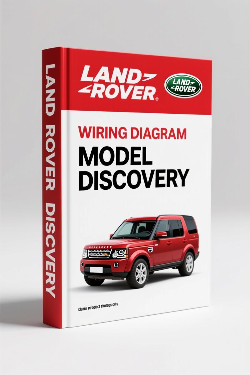
Land Rover Discovery 1995 Electrical Schematic – Factory Manual
Original price was: $29.80.$20.00Current price is: $20.00.
Factory electrical troubleshooting manual for 1995 Land Rover Discovery. 509 pages with complete wiring diagrams, diagnostic procedures, and component locations.
Description
Land Rover Discovery 1995 Electrical Schematic – Factory Diagnostic Manual
You’ve got a 1995 Discovery that’s blowing fuses, refusing to start, or flickering lights like a disco. I’ve been there. Electrical gremlins in these trucks don’t care about your weekend plans. Without a factory schematic, you’re chasing wires blind. This 509-page Land Rover Discovery 1995 Electrical Schematic manual is the exact documentation the factory issued to dealers. It’s not a Chilton’s rehash or a blurry PDF scan. It’s the original OEM print that shows every connector, every ground point, every wire color, and every diagnostic sequence Land Rover intended. I’ve used it on a 300TDi that had a parasitic drain that took three aftermarket diagrams to misdiagnose. This manual fixed it in one afternoon.
Injection System: Multi-Point Injection (MFI/V8 and MFI/T16) Wiring
The manual dedicates a full section to the multi-point fuel injection systems. You get separate schematics for the MFI/V8 and the MFI/T16. Each diagram shows the ECM pinout, injector circuits, airflow meter connections, and the idle speed control valve wiring. The 1995 Discovery uses a Lucas 14CUX or 14CU system depending on the engine. The manual lists the exact test points and voltage readings at the ECU connector. Page 73 (approximate, check the index) covers the injection relay and fuse allocation. If you’re swapping injectors or chasing a no-start, this section saves you from buying a new ECM that wasn’t broken.
Charging and Starting Circuit: Alternator, Starter, and Battery Connections
Charging system failures on the Discovery are common after 20 years – corroded fusible links, bad alternator brushes, or a starter solenoid that grounds out. The manual includes a dedicated “Démarrage et charge” chapter with the full starting circuit: starter motor solenoid terminals, alternator B+ and D+ wires, battery voltage sensing, and the ignition switch positions. It also shows the charge warning light circuit. I’ve seen DIYers replace a perfectly good alternator because they didn’t check the bulkhead connector pin 30. That’s on page 85 of this manual. The wiring diagram includes the 1995-era Lucas alternator regulator wiring – something aftermarket manuals often get wrong.
Cruise Control: Factory Wiring Diagram and Diagnostic Sequence
Cruise control on the Discovery uses a vacuum pump and electronic control module. The manual’s “Régulateur de vitesse” section breaks down the entire circuit: the control switch, brake pedal switch, clutch switch (manual), speed transducer, and the vacuum solenoid. It includes a diagnostic flow chart that steps you through checking the vacuum supply, electrical continuity, and module power. Without this, you’re guessing which component is dead. I’ve used it to trace a broken wire inside the steering column harness that three scan tools couldn’t find. The manual also lists the resistance values for the speed sensor – page 108.
Heater and Air Conditioning: Electrical Circuit Breakdown
The heater and A/C section covers the blower motor resistor pack, the A/C compressor clutch relay, the thermostatic switch, and the pressure switch circuit. The 1995 Discovery uses a R134a system with a cycling clutch. The manual shows the full power distribution from the fuse box (fuse 7, 15A) to the blower switch, then to the resistor pack. It also includes the wiring for the recirculation flap motor and the interior temperature sensor. I’ve seen a lot of blown A/C fuses because the compressor clutch coil shorts – the manual gives you the coil resistance spec (3.2 ohms at 20°C) so you can test it before replacing the compressor.
Lighting and Indicator: Headlamp, Tail Lamp, and Interior Light Circuits
The lighting section covers every exterior lamp: headlamps (dip and main beam), tail lamps, brake lights, turn signals, reverse lights, rear fog lights, and the interior courtesy lights. The manual includes a separate page for the “Feux de stop” (brake lights) showing the switch on the pedal box, the trailer wiring interface, and the relay. For the 1995 Discovery, the headlamp circuit uses a relay controlled by the lighting switch. The manual shows the wire colors – green/red for dipped beam, blue/red for main beam. If you’re replacing a headlamp switch or chasing a short that kills the dash lights, this section is your map.
Source Authenticity: Factory Land Rover, Not Aftermarket
This is an original Land Rover publication, printed in 1995. It’s not a third-party recompilation or a generic wiring diagram. The manual uses the same part numbers, connector views, and diagnostic procedures that Land Rover training centers taught. Aftermarket manuals often omit the ground locations or mislabel the relay positions. On a Discovery, grounding points are critical – the engine block ground, the chassis ground near the battery, and the auxiliary ground behind the glovebox. The manual shows them all. You can cross-reference it with the Land Rover Discovery 2002 Electrical Circuit Diagrams for later changes, but for a 1995, this is the definitive source.
Fuse Box and Relay Locations: Page-by-Page Reference
The manual includes a dedicated index for fuse boxes and relays. There are three fuse boxes on the 1995 Discovery: under the hood (engine compartment), under the dashboard (passenger side), and on the left side of the loadspace. The manual lists each fuse rating, circuit protected, and the relay identification. For example, the main relay (MFI) is in the engine compartment fuse box – position R1, a 30A relay. The manual also includes the “Feux de recul” (reverse light) relay location. I’ve had to replace a corroded relay socket on a 1995 Discovery – the manual’s terminal layout saved me from cutting the wrong wires.
If you’re working on a 1995 Discovery, you need this manual. It’s 509 pages of OEM wiring diagrams, component locations, and diagnostic procedures. The manual covers the 300TDi, V8, and 2.0 Mpi petrol engines. For a related model, see the Land Rover Discovery 2003MY Electrical Circuit Diagrams or the Land Rover Discovery 1995 Workshop Manual for mechanical repairs. For background on automotive electrical systems, the Automotive Industry Overview provides context, and the Automotive Battery section covers battery specs. But for the Discovery’s wiring, this is the only manual you need. Access the Factory Manual now.
- Does this manual cover the 1995 Discovery with the 300TDi engine?
- Yes. The manual includes specific schematics for the 300TDi, including the glow plug circuit, injection pump wiring, and the ECM.
- What tools do I need to use this manual effectively?
- A digital multimeter, a test light, a wiring probe, and a good set of trim tools. The manual assumes you have basic electrical knowledge. It does not include step-by-step torque specs because it’s an electrical schematic, not a workshop manual. The Land Rover Discovery 1995 Workshop Manual covers mechanical torque values.
- How are the wiring diagrams organized?
- Each diagram flows from top (power source) to bottom (ground). Components are shown in their functional group. The manual includes a symbol legend on page 2. Connector views are provided for the major control units, and wire colors are labeled in English and French.
- Can I use this manual for a 1996 Discovery?
- The 1996 model year had minor changes to the interior lighting and the ABS system. While many circuits are identical, the 1996 manual is a separate publication. For accurate diagnostics on a 1996, order the Land Rover Discovery 2002 Electrical Circuit Diagrams (which covers 1996-2002) or the specific 1996 edition.
Additional information
| Brand | Land Rover |
|---|---|
| Language | English |
2 reviews for Land Rover Discovery 1995 Electrical Schematic – Factory Manual
You may also like…
-
Sale!
Land Rover Defender 2007 Electrical Schematic – 338-Page OEM Circuit Data
Original price was: $53.20.$40.00Current price is: $40.00. -
Sale!
Land Rover Defender Workshop Manual – 1213 Pages of Factory Specs
Original price was: $62.80.$40.00Current price is: $40.00. -
Sale!
Land Rover Freelander 2003 Wiring Diagram – Factory Electrical Schematics
Original price was: $58.95.$45.00Current price is: $45.00. -
Sale!
Land Rover Defender 1996 Workshop Manual – Factory Specs for 300Tdi
Original price was: $63.20.$40.00Current price is: $40.00.
Related products
-
Sale!

Acura Integra 1998 Service Manual – 1891 Pages Factory OEM Documentation
Original price was: $31.75.$25.00Current price is: $25.00. -
Sale!

2004 Acura TSX Wiring Diagram – 73-Page Factory Electrical Schematics
Original price was: $15.88.$9.99Current price is: $9.99. -
Sale!

Acura NSX 1991 Service Manual – 1420 Pages OEM
Original price was: $102.05.$65.00Current price is: $65.00. -
Sale!

International 1000-3000 Series Operators Manual – 132 Pages of OEM Specs
Original price was: $14.40.$10.99Current price is: $10.99.
diy_master –
Excellent quality! The PDF looks clean. It helped me to repair my Land Rover Rover transmission. Saved my repair job! Thanks.
workshop_guy –
Five stars! The PDF quality is excellent. A must-have for any Land Rover Rover DIYer doing repairs. Saves me hundreds of dollars.