
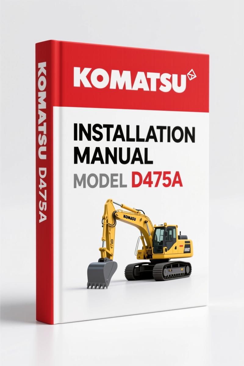
Komatsu D475A, D475ASD Installation Manual – Factory Field Assembly Specs
Original price was: $58.50.$45.00Current price is: $45.00.
OEM installation manual for Komatsu D475A/D475ASD. 240 pages of factory assembly specs, torque tables, and hydraulic cylinder procedures.
Description
Komatsu D475A, D475ASD Installation Manual – Factory Assembly Specs
You’ve got a D475A or D475ASD delivered in multiple shipping units. The dealer wants to charge a week’s labor to bolt it together. You think you can save money with a couple of wrenches and a prayer. Stop. This machine weighs over 100 tons fully assembled. One wrong torque on a track shoe bolt or a hydraulic cylinder mount, and you’re looking at a catastrophic failure that will cost more than the dealer’s fee. The Komatsu D475A, D475ASD Installation Manual is not a suggestion. It is the only document that tells you exactly how to reassemble this machine from the shipping configuration back to operational condition. 240 pages of factory procedure. No aftermarket guesswork.
Tightening Torque: Why 26 Pages of Specs Matter
The manual devotes a dedicated section to tightening torque. This is not a generic table pulled from a third-party database. Komatsu engineers calculated each value for the specific bolts, materials, and loads in this machine. The TIGHTENING TORQUE section lists every fastener you will touch during assembly – from the blade lift hydraulic cylinder mounts to the track shoe bolts. Using the wrong torque on a cylinder head bolt or a pivot chamber plug can lead to oil leaks or structural failure. The manual includes both Nm and ft-lb values, so you don’t have to convert. Stick to the spec.
Precautions for Field Assembly
The preface makes one thing clear: safety is not optional. Before a single bolt is turned, the work supervisor must hold a safety meeting, designate a crane signal man, and ensure every worker wears the right gear. This section outlines the supervision system – work leader, crane director, interpreter if needed – and it is not filler. When you are slinging a 10-ton blade lift cylinder with a crane, the margin for error is zero. The manual also stresses that engine must be run before installing work equipment, so you need a complete inspection first. Follow these precautions or don’t start the job.
Tools List for Field Assembly – Required Gear
Page 13 through 16 list every tool required for the job, including part numbers for Komatsu special tools. This is not a suggestion to “use common sense.” The SKETCH OF TOOLS section shows exactly what each tool looks like and how it engages with the fastener. If you do not have the correct torque wrench with the proper adapter, you cannot achieve the specified torque. The manual also covers coating materials – which threadlocker or anti-seize to apply to which bolts. Using the wrong coating can change the effective torque by 20% or more. Get the right tools first.
Assembly Procedure: From Track Shoe to Exhaust Pipe
The core of the manual is the A section, covering 26 individual assembly steps. It starts with A-1: Setting of track shoe – not just dropping the track on the ground, but aligning it so the final drive splines engage correctly. A-3 details installation of the blade lift hydraulic cylinder, which requires precise alignment and torque on the trunnion pins. A-10 covers track shoe installation with a specific sequence and torque pattern. A-17 shows how to install the giant ripper shank – a part that can crush a person if it slips. Each step includes a time estimate and a list of required equipment from the KIT LAYOUT DIAGRAM. Following the sequence is critical; skipping A-6 (adding oil to pivot chamber) before bleeding the cylinders (A-25, A-26) will fill the system with air. The manual also includes procedures for the D475ASD (Superdozer) variant, such as checking the auto-reset system (A-21) and adjusting the blade tilt angle limit (A-20).
Bleeding Air from Hydraulic Cylinders: Factory Procedure
A-25 and A-26 cover bleeding air from the hydraulic cylinders and the work equipment pump. This is where most field assemblies fail. If you don’t purge the air properly, the machine will have spongy controls and can damage pump seals. The manual specifies the exact valve sequence and minimum cranking time. Torque values for bleed port plugs are listed in the TIGHTENING TORQUE section. Do not improvise.
Check and Maintenance Procedures After Completion
After assembly, the M section walks you through checks and initial start-up. M-1: Check and adjustment of operator’s cab – seat position, controls, visibility. M-2: Inspection of machine monitor – verify all warning lights and gauges function. M-3: No-injection cranking of engine – prime the oil system before first fire. M-4: Setting procedure of user adjust mode – calibrate the joystick response. M-5: Flushing of hydraulic circuit – remove any debris introduced during assembly. Skipping M-5 will send metal shavings through your main pump. Appendix 2 includes precautions for initializing the VHMS controller; fail to do this and your telematics won’t work.
This is a 240-page manual. It contains the exact information you need to put a D475A or D475ASD together safely and correctly. The FIELD ASSEMBLY INSPECTION REPORT forms at the end are the same checklists Komatsu dealers use to sign off on a build. Use them.
If you are working on other large Komatsu equipment, check the related manuals: Komatsu WD900-3 Installation Manual – Field Assembly Specs & OEM Torque, Komatsu WF550A-3 Installation Manual – OEM Factory Assembly Specs, and Komatsu HD1500-5 Installation Manual – 199-Page Factory Assembly Guide. For general knowledge on how a manual transmission works, see Manual Transmission and Manual Transmission on Wikipedia.
Don’t rely on aftermarket procedures or a quick YouTube video. Access the Factory Manual and get the real specifications.
- Can I use this manual for the D475A-5E0 with serial number below 30001?
- No. This manual covers serial numbers 30001 and up.
- Why does the manual include a section on “Setting of track shoe” if the tracks are already assembled when shipped?
- The tracks are often removed for transport to meet size and weight regulations. The manual covers reinstallation of track shoes (A-1 and A-10) with the correct sequence and torque pattern. It also details how to check track tension (A-11) – a step many field assemblers skip, leading to premature track wear or derailment. Additionally, the track shoe bolts are listed in the torque section, and using the wrong torque can strip the threads in the final drive hub. The procedure is not obvious; the manual shows the exact method to lift the machine, position the track, and tension it using the measuring tool from the tools list. Without this procedure, you risk damaging the undercarriage within the first 50 hours of operation. That is why it is included even if the tracks come as a separate unit.
Additional information
| Brand | Komatsu |
|---|---|
| Language | English |
2 reviews for Komatsu D475A, D475ASD Installation Manual – Factory Field Assembly Specs
You may also like…
-
Sale!

Komatsu PC5500E-6 Workshop Manual – 1378 Pages
Original price was: $150.00.$100.00Current price is: $100.00. -
Sale!
Komatsu D65EX, D65PX, D65WX Workshop Manual – 2820 Pages
Original price was: $108.75.$75.00Current price is: $75.00. -
Sale!
Komatsu HD1200 1980 Workshop Manual – Factory Specs & Procedures
Original price was: $91.50.$75.00Current price is: $75.00. -
Sale!

Komatsu PC600LC-6 Workshop Manual – Factory Service Data for 732-Page Excavator Guide
Original price was: $112.80.$80.00Current price is: $80.00.
Related products
-
Sale!

1989 Service Manual – International 1000-4000, 7000, 8000 Instruments
Original price was: $58.80.$40.00Current price is: $40.00. -
Sale!

Acura NSX 1991 Service Manual – 1420 Pages OEM
Original price was: $102.05.$65.00Current price is: $65.00. -
Sale!
1992 Electrical Schematic – International 1000/3000/4000/2554 OEM Wiring Diagrams (132 Pages)
Original price was: $26.40.$20.00Current price is: $20.00. -
Sale!

2005 Parts Catalog – International NGD 3.0 L Engine (77 pages)
Original price was: $44.70.$30.00Current price is: $30.00.
Charles W. –
I am so happy with this manual. Immediate link after payment. Contains detailed wiring diagrams for Komatsu. I will definitely buy again.
diy_master –
This is exactly what I needed. Quick access after payment. It assisted me to repair my Komatsu D475A, electrical system. I will definitely buy again.