
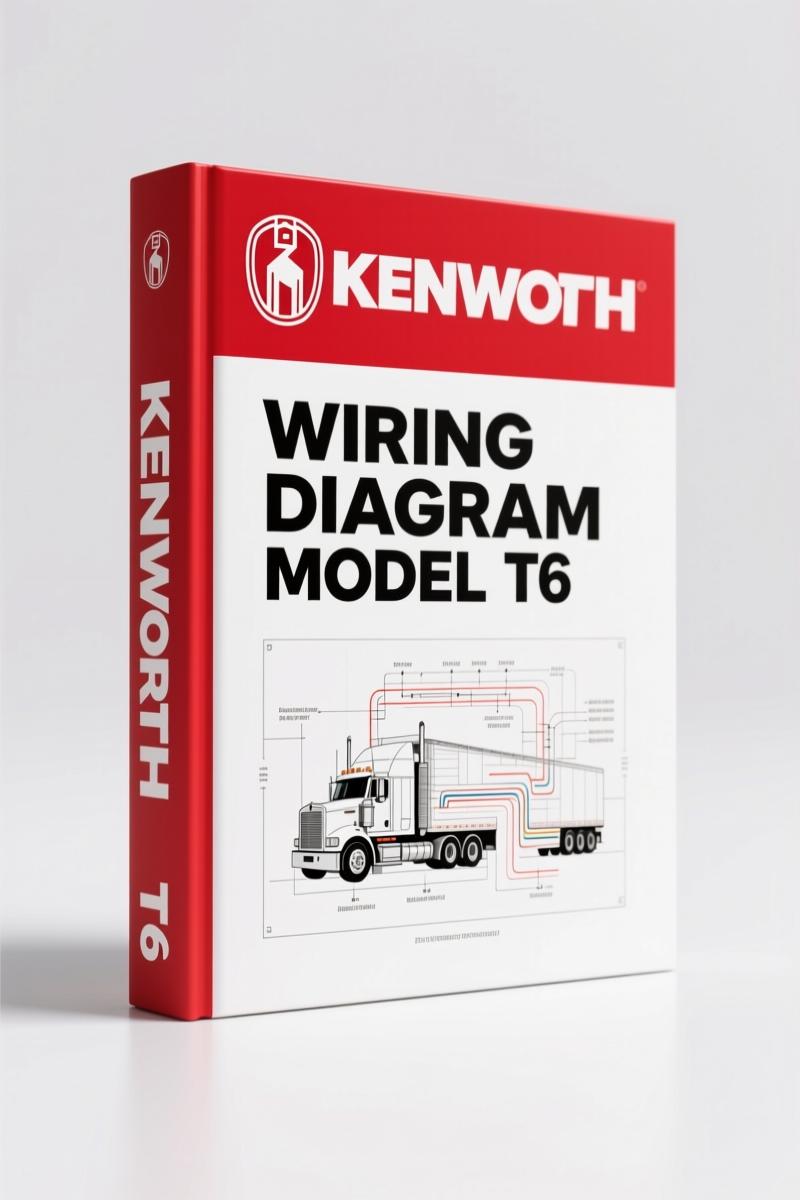
Kenworth T4, T6, T9 2011 Wiring Diagram – 78-Page Factory Electrical Guide
Original price was: $57.15.$45.00Current price is: $45.00.
OEM Kenworth T4, T6, T9 2011 wiring diagram – 78 pages of factory electrical schematics for professional technicians.
Description
Kenworth T4, T6, T9 2011 Wiring Diagram – OEM Factory Schematics
You’ve got a T4, T6, or T9 on the lift with an electrical ghost – maybe a trailer light that won’t fire or an ABS fault that clears and comes back. You pull out a third-party wiring diagram and the wire colors don’t match, pinouts are missing, and you spend an hour tracing a circuit that should take twenty minutes. That’s exactly why this factory wiring manual exists. It’s the original PACCAR release, not some scanned reprint with faded lines. If you’re working on a 2011 Kenworth conventional, this 78-page document is the only source you should trust for a clean repair.
Master Wiring Diagram – Page 2 Coverage
Page 2 gives you the master wiring diagram for all conventional models in this series. That single sheet shows how every subsystem ties into the main harness – starter, alternator, J1939 backbone, cab power distribution. If you’re chasing a no-start on a T6, start here. The schematic uses standard PACCAR drawing numbers (P94-1730), so cross-referencing with actual truck components is straight. No guesswork about which relay feeds the ECM. Need the charge pressure? That’s page 73 of the manual, but the master diagram points you there. Aftermarket manuals often skip this overview layer, leaving you to piece together systems blind.
ABS, Bendix Gen 6 – Full System Schematics
Three pages (page 4) dedicated to ABS, ATC, HSA, ESP, and active cruise braking. This section covers the Bendix Gen 6 controller and its wheel speed sensors, modulator valves, and trailer ABS interface. You’ll find the exact pin assignments for the J1939 CAN bus link and the trailer ABS power circuit. One wrong splice here and you’ll get a dash light that won’t clear without a scan tool. The factory diagram includes the revision mark (Rev. – for most, Rev. B on some), so you know you’re looking at the current production spec. If you’re swapping an ABS modulator, verify the pinout on page 4 before cutting any wires.
Engine Diagrams: ISX ADR 80/03 and Others
Four separate engine wiring sections cover ISX ADR 80/03 (page 32), ISX ADR 80/02 (page 36), ISX/Signature ADR 80/00 (page 40), and the ISM11e5 (T403) on page 44. Each one has its own ECM connector view, injector harness routing, and sensor locations. The ISM11e5 diagram runs five pages and includes the common rail pressure control circuit. I’ve seen third-party versions merge these into one generic Cummins diagram – that’s how you fry an ECM by wiring a 5-volt sensor to a 12-volt feed. Stick with the factory page for your exact engine rating. The manual also notes ‘All diagrams are valid for vehicles built from January 2011,’ so you’re covered for mid-year production changes.
Gauges, Warning Lights and Alarms – Page 49
Page 49 maps the instrument cluster, warning lights, and alarm circuits. Four pages cover everything from low air pressure warning to the brake pad wear indicator. Need to add a back-up alarm? The wire color code key on the title page (B=Black, R=Red, L=Blue, etc.) lets you decode the harness without a meter. The document also includes a dedicated page for the door open/park brake OFF warning light (page 31) – a common fault on T4 models that’s usually a broken wire in the door jamb. The factory schematic shows the exact splice point. Aftermarket diagrams often omit these auxiliary warning circuits because they think they’re optional.
Wiring Colour Codes – Avoid Wrong Connections
The color key is printed on page 1 and repeated on page 2. Ten colors with two-letter codes for stripe identification. Example: L/E = Blue base with Grey stripe. That’s critical for Kenworth’s harness because they use a consistent scheme across all T4/T6/T9 models. If you’re splicing into the trailer lighting circuit (Narva or Phillips, pages 72-74), match the stripe exactly. One misread stripe on a Phillips bulkhead connector can ground a marker light circuit and blow a fuse. Also listed: the low fuel alarm (page 67) and two-speed axle switch (page 78) – both common headache points on older trucks.
Why Factory OEM Wiring Diagrams Matter
This isn’t a reprint from a third-party publisher. It’s the official PACCAR maintenance manual, CAT number 8314 469 07/11, printed in July 2011. Each drawing carries the proprietary notice: “This Drawing and the information contained herein is proprietary to PACCAR Inc.” You’re not getting a copy-of-a-copy with blurred lines or missing revisions. Every page includes a revision letter and date stamp. If you’ve wasted time on an aftermarket schematic that shows a wire color that doesn’t exist in your harness, you know the cost. For the fleet mechanic, this manual means fewer comebacks. For the DIY owner-operator, it means not paying a dealer $150 to read a wiring diagram.
Count the pages: 78. That covers every system from the Ashdown battery isolation switch to the Lumens Bluetooth module. No fluff, no generic theory – just the factory schematics you need to trace a circuit, verify a splice, or install an accessory. If you’re working on a Kenworth T4, T6, or T9 built after January 2011, pull this manual open before you touch a wire. Related manuals you might need: Kenworth P94 Wiring Diagram – Factory ABS & Trailer ABS Schematic, Kenworth K108 K200 Wiring Diagram Manual, and Kenworth T170,T270,T370 2011 Installation Manual – OEM Specs. For more background on interpreting heavy-truck schematics, check Automotive Wiring references.
- Does this manual cover the ABS trailer wiring separately?
- Yes. Page 4 has a dedicated five-page section for ABS, trailer ABS, and active cruise braking. It includes the Bendix Gen 6 controller and the trailer ABS power circuit.
- What year Kenworth trucks does this apply to?
- It covers 2011 T4, T6, and T9 conventional models built from January 2011 onward. The manual says diagrams are valid until superseded.
- How many pages are in the wiring diagram manual?
- 78 pages, each one a factory schematic or supplementary diagram.
- Are the wiring color codes listed?
- Yes. A full color key is on pages 1 and 2, with base and stripe codes like L/E (blue/grey) and abbreviations for black, red, green, etc. Never trust aftermarket color translations. This manual uses the exact PACCAR code.
Don’t chase electrical problems with a blurry photocopy. You’ve got a truck that needs to run, and you need the right diagram the first time. Access the Factory Manual – the original OEM PACCAR wiring diagrams for Kenworth T4, T6, T9 2011 models. Install it on your tablet or print the pages you need. Your harness will thank you.
Additional information
| Brand | Kenworth |
|---|---|
| Language | English |
3 reviews for Kenworth T4, T6, T9 2011 Wiring Diagram – 78-Page Factory Electrical Guide
You may also like…
-
Sale!
Kenworth K108 & K200 Wiring Diagram – 48-Page OEM Manual
Original price was: $62.40.$40.00Current price is: $40.00. -
Sale!
Kenworth T470 Technical Manual – Body Builder Specs for Fleet Mechanics
Original price was: $35.25.$25.00Current price is: $25.00. -
Sale!
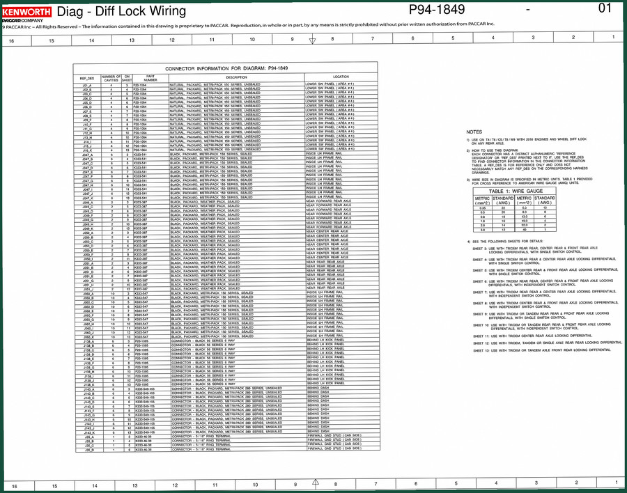
Kenworth P94 Wiring Diagram – Factory ABS Schematics (14 Pages)
Original price was: $22.40.$16.00Current price is: $16.00. -
Sale!

Kenworth T170, T270, T370 2011 Installation Manual – OEM Body Builders Specs
Original price was: $38.70.$30.00Current price is: $30.00.
Related products
-
Sale!

International 1000-3000 Series Operators Manual – 132 Pages of OEM Specs
Original price was: $14.40.$10.99Current price is: $10.99. -
Sale!

2011 Parts Catalog – International Truck OE Parts Documentation (1786 Pages)
Original price was: $34.50.$25.00Current price is: $25.00. -
Sale!
1993 Electrical Schematic – International 1000/3000/4000 Bus Chassis OEM Wiring Diagrams
Original price was: $29.26.$22.00Current price is: $22.00. -
Sale!
1993 Operators Manual – International Bus 1000-3000 OEM Specs
Original price was: $12.30.$7.99Current price is: $7.99.
diy_master –
Excellent factory service manual. The text is searchable and well indexed. Contains detailed bolt torque specs for Kenworth. I will definitely buy again.
gearhead88 –
Great factory service manual. Instant access after checkout. A must-have for any Kenworth T4, mechanic doing maintenance. Saved my weekend project! Thank you.
Richard G. –
Great buy! The document looks clean. Contains clear wiring diagrams for Kenworth. Saved my repair job! Thank you.