
Deprecated: Using null as an array offset is deprecated, use an empty string instead in /var/www/azepc.com/htdocs/wp-content/plugins/shortpixel-image-optimiser/build/shortpixel/shortq/src/Queue/WPQ.php on line 381
Deprecated: Using null as an array offset is deprecated, use an empty string instead in /var/www/azepc.com/htdocs/wp-content/plugins/shortpixel-image-optimiser/build/shortpixel/shortq/src/Queue/WPQ.php on line 381
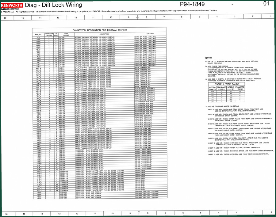
Kenworth P94 Wiring Diagram – Factory ABS Schematics (14 Pages)
Original price was: $22.40.$16.00Current price is: $16.00.
Official 14-page Kenworth P94 wiring diagram for ABS and trailer ABS. Includes circuit position charts, connector reference, and sheet selection tables.
Description
Kenworth P94 Wiring Diagram – Factory ABS and Trailer ABS Schematic
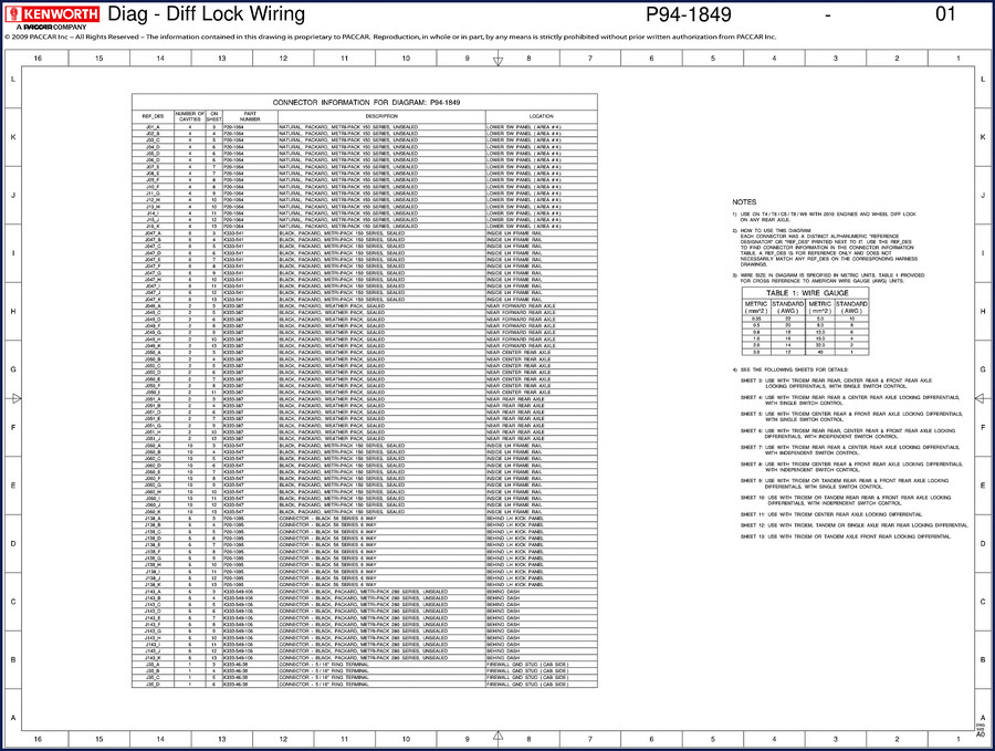
If you have ever tried to trace an intermittent ABS fault on a Kenworth P94 using a copied-and-pasted aftermarket diagram, you already know how it ends. Wrong pin assignments, missing twisted-pair notes, and connector part numbers that don’t match what is under the dash. This Wiring Diagram is the real thing – a factory-issued Bendix ABS schematic that Kenworth themselves used. 14 pages, no reprints, no guesswork. Let me walk you through what is inside and why you want this on your bench instead of some PDF from a forum.
ABS Wiring: What This 14-Page Diagram Covers
The diagram is built around the Bendix ABS system, paired with NAMUX II instrumentation and 2007 engines. But it does not just show wires – it includes the full reference designator system. Every connector has a unique alphanumeric code. You will find circuit position charts for 22 different connector bodies, ranging from Deutsch HDP20 sealed connectors to the SAE J560 and ISO 3731 trailer receptacles. Table A on sheet 3 breaks out cab ABS variations: advanced, premium, and standard systems. Table B gives you seven trailer harness variations, from no trailer connections to full J560 + ISO 3731 with hotline. That is the kind of detail that saves you from ordering the wrong harness or chasing a ground that does not exist.
How to Use the Reference Designator System
Page 1 of the diagram lays out the general notes. Pay attention to note 2: each connector gets a reference designator (Ref Des) like J01A. You use that code to look up the connector information table on page 2. The table tells you sheet number, number of cavities (e.g. 14), part number (e.g. HDP26-18-14SE), color, and location on the vehicle – upper left hand side, for instance. If you try to work without that table, you are guessing. I have seen guys splice into the wrong cavity because they assumed pin 1 was where it always is. Not on a Deutsch connector with a 2B position. The reference designator system removes that guesswork. Use it.
14 Pages of Factory Connections
Yes, all 14 pages are dense. The first page gives the overview and general notes. Page 2 is the connector information table – that is the index you will fold open and keep beside the truck. Sheets 3 through 6 cover cab ABS variations (advanced, premium, standard). Sheets 7 through 13 cover the trailer harness variations. Each sheet has its own set of circuit position charts and connector drawings. Page 14 is not listed in the OCR, but the diagram ends there. The OCR shows component information for harness P94-1754-000 on page 2. That is the specific harness this diagram supports. If you have a different dash number, check the variation tables – you may need the -002 or -003 sheet. do not assume one harness fits all.
Read the General Notes First
Note 3: twisted pairs are marked with a specific symbol. XX denotes twisted pair of jacketed wires. WE denotes twisted quadruplet. If you ignore those markings, you risk crosstalk in the ABS sensor lines. Note 4: X designates a reference point on another sheet. Note 5: supersedes P94-1642-000. That means this is the updated version. If you have an older truck with the -1642 diagram, the connector locations may have changed. do not mix them. Note 1 also restricts use to T6/T8/W9/C5 with NAMUX II and 2007 engines. If your P94 is a 2006 model, the wiring might differ – I cover that in the FAQ.
Connector Identification: Using the Part Numbers
Every connector in the diagram has a full part number. For example, K333-549-104 appears on the circuit position chart for one of the Deutsch connectors. You can use that number to physically identify the connector on the truck. The diagram also includes pin numbers (e.g. PIN 1, PIN 2) and mating part references like 1-967325-2. That level of detail is why OEM documentation is worth the money. Aftermarket diagrams often leave out the part numbers or use generic descriptions. You end up spending an hour staring at a connector trying to figure out which cavity is which. With this manual, you can verify the connector body before you even touch a multimeter.
Why OEM Beats Aftermarket Copies
I have worked on enough trucks to tell you that third-party wiring diagrams are a liability. They simplify the drawing, omit the twisted-pair note, or swap pin positions because the author did not have access to the actual connector. This manual came from Kenworth’s own engineering division. The circuit position charts are exact. The variation tables cover every configuration Kenworth sold. If you are wiring a trailer ABS on a P94, you need to see the ISO 3731 receptacle pinout as shown on sheet 9 or 10. That is not something a generic diagram will give you. Automotive Wiring is a field where accuracy can mean the difference between a functional brake system and a truck that fails inspection.
Workshop Tips from a 28-Year Tech
When you get this diagram, print it out in color – the twisted-pair symbol is easy to miss in grayscale. Tape page 2 to the wall above your bench. Before you probe any connector, find its Ref Des in the table and verify the cavity count. Also note the X reference points; if you see X next to a wire, flip to the referenced sheet before you cut anything. And for the love of electrical tape, do not assume ground is ground – some circuits use the chassis return, others run a dedicated ground wire back to the ECU. The diagram shows every path. Use it.
For related Kenworth wiring, check out the Kenworth P94 Diff Lock Wiring Diagram P94-1849 if you need the diff lock circuit. For a broader view of the electrical system, the Kenworth T4 T6 T9 2011 Wiring Diagram Manual covers later models. If you are working on a K108 or K200, see the Kenworth K108 K200 Wiring Diagram Manual.
- Does this diagram cover the engine ECM or just ABS?
- It covers only the Bendix ABS and trailer ABS systems. No engine ECM wiring is included.
- Can I use this on a 2006 Kenworth P94?
- General note 1 specifies 2007 engines with NAMUX II instrumentation. If your 2006 truck has the same Bendix ABS and NAMUX II, the connector pinouts may be identical, but I recommend verifying the superseded diagram number. This diagram supersedes P94-1642-000; if your truck uses that older number, the harness layout may have changed. Check the reference designator table against your actual connector locations before making any repairs. There were minor harness routing changes between 2006 and 2007 production years that could affect sheet numbers 7–13 for trailer variations.
- How do I interpret the twisted-pair notation?
- Look for symbols near the wire lines on the sheets. XX indicates a twisted pair of jacketed wires. WE indicates a twisted quadruplet. These are used for wheel speed sensor circuits to reduce electrical noise. Do not untwist them more than necessary.
- Is this the same as the P94-1642 diagram?
- No. This diagram supersedes P94-1642-000. The connector part numbers and sheet numbering are different. Use only the version that matches your harness dash number.
If you want to stop troubleshooting electrical faults by swapping parts and start tracing them with the actual factory schematic, Access the Factory Manual now. Put this 14-page Kenworth P94 wiring diagram on your tablet or print it out – your meter and your sanity will thank you. Automotive Industry Overview shows how OEM documentation like this drives professionalism in the field.
Additional information
| Brand | Kenworth |
|---|---|
| Language | English |
4 reviews for Kenworth P94 Wiring Diagram – Factory ABS Schematics (14 Pages)
You may also like…
-
Sale!
Kenworth T470 Technical Manual – Body Builder Specs for Fleet Mechanics
Original price was: $35.25.$25.00Current price is: $25.00. -
Sale!
Kenworth T4, T6, T9 2011 Wiring Diagram – 78-Page Factory Electrical Guide
Original price was: $57.15.$45.00Current price is: $45.00. -
Sale!
Kenworth K108 & K200 Wiring Diagram – 48-Page OEM Manual
Original price was: $62.40.$40.00Current price is: $40.00. -
Sale!

Kenworth T170, T270, T370 2011 Installation Manual – OEM Body Builders Specs
Original price was: $38.70.$30.00Current price is: $30.00.
Related products
-
Sale!

1992 Electrical Schematic – OEM Wiring Diagrams for International 1000-3800
Original price was: $24.48.$18.00Current price is: $18.00. -
Sale!
1995 Operators Manual – International 1000-4000 Series | OEM Documentation
Original price was: $12.49.$9.99Current price is: $9.99. -
Sale!
1991 Electrical Schematic – 112-Page OEM Wiring Diagram for International 1000-3000 Series
Original price was: $22.75.$17.50Current price is: $17.50. -
Sale!
1993 Electrical Schematic – International 1000/3000/4000 Bus Chassis OEM Wiring Diagrams
Original price was: $29.26.$22.00Current price is: $22.00.
Charles W. –
Five stars! The pages are clean and easy to navigate. Every spec sheet is included for Kenworth P94. Saves me hundreds of time.
diy_master –
Great OEM spec sheet. The PDF is very clear. It assisted me to troubleshoot my Kenworth P94 electrical system. Saved my repair job! Thanks.
Michael T. –
I am very pleased with this transaction. The document looks clean. A must-have for any Kenworth P94 DIYer doing maintenance. I will recommend this shop to others.
Richard G. –
This is just what I was looking for. It is very easy to read on my laptop without blur. A must-have for any Kenworth P94 owner doing repairs. Highly recommended for mechanics.