
Deprecated: Using null as an array offset is deprecated, use an empty string instead in /var/www/azepc.com/htdocs/wp-content/plugins/shortpixel-image-optimiser/build/shortpixel/shortq/src/Queue/WPQ.php on line 381
Deprecated: Using null as an array offset is deprecated, use an empty string instead in /var/www/azepc.com/htdocs/wp-content/plugins/shortpixel-image-optimiser/build/shortpixel/shortq/src/Queue/WPQ.php on line 381
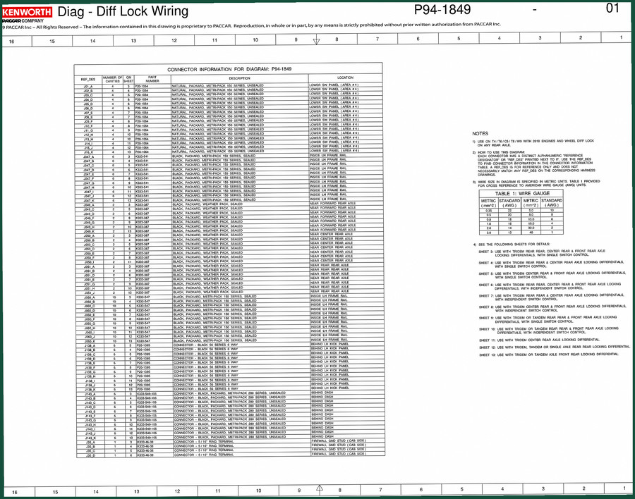
Kenworth P94 Electrical Schematic – 13-Page OEM Wiring Diagram
Original price was: $19.35.$15.00Current price is: $15.00.
Kenworth P94 Electrical Schematic – 13 OEM pages covering diff lock wiring, connector locations, and PACCAR-sourced diagrams.
Description
Kenworth P94 Electrical Schematic – Diff Lock Wiring and Connector Data
If you are chasing a diff lock fault on a Kenworth P94 and find yourself probing wires with a test light hoping you hit the right circuit, you are losing billable hours and risking a short. I have seen guys replace three solenoids and a switch module before they break down and buy the schematic they should have started with. That is what this 13-page Kenworth P94 Electrical Schematic is built for: one pass, no guessing. Every connector location, cavity count, and part number in this print comes directly from PACCAR’s proprietary system – not a third-party redraw. The day that becomes your workbench reference, the diff lock stops being a headache and starts being a ten-minute pin check.
Diff Lock Wiring: What the 13 Pages Cover
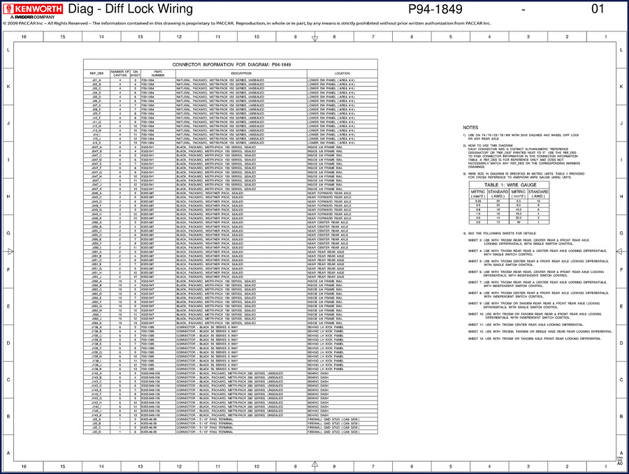
This is not some generic wiring color chart. Sheet 1 of the schematic is dedicated to the diff lock circuit – labeled “KENWORTH Diag – Diff Lock Wiring 01” with a PACCAR proprietary notice. From there, the remaining pages break down every connector in the path. Reference designators like J01 through J16 and J047 series are mapped to specific cavity counts (4, 6, 12 cavity), part numbers (P20-1064, K333-541), and exact truck zones: lower switch panel area #4, inside LH frame rail, near forward rear axle. Need to know if a pin is dead? Flip to the sheet that lists that connector – you get the wire location on the page and the mating part. That kind of data kills the “maybe it’s pin C” routine.
Connector Reference Table – Not a Generic List
Page 1 of the schematic carries a connector information table that lists every REF DES, number of cavities, sheet number, part number, description, and location. For example, J01 is a 4-cavity natural Packard Metri-Pack 150 series unsealed connector on the lower switch panel. J047 is a 6-cavity black sealed connector inside the LH frame rail. That distinction – sealed vs unsealed – matters when you are tracing a corrosion problem. Aftermarket manuals often omit the seal type and just give a generic “connector near frame”. This document tells you exactly which part to order if a terminal gets mangled. Automotive Wiring fundamentals like terminal retention and weatherpack sealing are critical on heavy trucks, and this schematic gives you the factory part numbers to do it right.
Who Needs This Schematic on the Bench?
Fleet mechanics working on P94 chassis. Owner-operators who maintain their own rig. Shop foremen who do not want a tech chasing a ghost ground for three hours. If you have a P94 with an intermittent diff lock or a switch that tests fine but the solenoid never clicks, you need the wiring path straight from the OEM. The schematic covers the lower switch panel connectors (area #4) where the diff lock switch terminates, the bulkhead pass-through, and the axle-end connectors J047 and J049. It also identifies sealed vs unsealed connectors – that tells you where water intrusion is likely. For a home garage truck owner, this print is the difference between throwing parts at it and fixing the actual broken wire.
OEM Print vs Aftermarket Redraws
I have seen aftermarket schematics that swap wire colors and shift pin locations because someone traced a harness with a continuity tester and guessed at the layout. That is dangerous on a truck with multiplex systems and high-current circuits. This document is a direct PACCAR production print – notice the copyright line: “The information contained in this drawing is proprietary to PACCAR. Reproduction strictly prohibited.” That is the hallmark of a factory document. Every connector part number, every cavity count, every location note (e.g., “LOWER SW PANEL (AREA #4)” or “INSIDE LH FRAME RAIL”) matches the original build sheet. If you need to verify a ground point or a power feed, you can trust the print. Check out the related Kenworth P94 ABS and TRLR ABS Wiring Diagram P94-1754 for more chassis electrical coverage, or the Kenworth T170/T270/T370 Body Builders Manual 2011 for body interface specs. The Kenworth T470 Body Builder Manual covers similar frame rail connector layouts.
7 Connector Families Charted
The OCR excerpt lists 27 unique connector entries across 7 series: J01–J16 (unsealed Metri-Pack 150 natural), J047 A–K (sealed Metri-Pack 150 black), J049 (sealed Weather Pack). Each entry includes the sheet page number where the connector appears. That means you can locate a specific J09 pin on sheet 7 and confirm its mate on sheet 8. For a mechanic, that cross-referencing is the difference between spending 20 minutes vs 2 minutes on a pin test. No reprints, no third-party transcription – just the original factory PDF.
FAQ
- Does this schematic cover any other Kenworth models besides the P94?
- No. This electrical schematic is specific to the P94 platform only. It does not cross over to T-series or other Kenworth models.
- What exactly is included in the 13 pages? I see diff lock wiring – does it show the whole truck harness or just that circuit?
- The 13 pages focus on the diff lock circuit and its associated connectors. You get the full wiring path from the switch panel connectors (J01–J16) through the frame rail connectors (J047 series) to the axle connector (J049). Each page shows a portion of the harness with all connector pinouts, cavity numbers, part numbers, and location notes. It does not contain every wire in the cab – it is a subsystem schematic. If you need the full body harness, the related Automotive Industry Overview page has resources that may point to broader OEM documentation. But for the diff lock, this is the exact print a PACCAR engineer used.
Stop chasing phantom voltage drops. Access the Factory Manual now and put the correct pin number on your meter lead.
Additional information
| Brand | Kenworth |
|---|---|
| Language | English |
3 reviews for Kenworth P94 Electrical Schematic – 13-Page OEM Wiring Diagram
You may also like…
-
Sale!
Kenworth T4, T6, T9 2011 Wiring Diagram – 78-Page Factory Electrical Guide
Original price was: $57.15.$45.00Current price is: $45.00. -
Sale!
Kenworth K108 & K200 Wiring Diagram – 48-Page OEM Manual
Original price was: $62.40.$40.00Current price is: $40.00. -
Sale!
Kenworth T470 Technical Manual – Body Builder Specs for Fleet Mechanics
Original price was: $35.25.$25.00Current price is: $25.00. -
Sale!

Kenworth T170, T270, T370 2011 Installation Manual – OEM Body Builders Specs
Original price was: $38.70.$30.00Current price is: $30.00.
Related products
-
Sale!

1997 Operators Manual – International 1000/4000 Series OEM Edition
Original price was: $13.49.$9.99Current price is: $9.99. -
Sale!

2004 Acura TSX Wiring Diagram – 73-Page Factory Electrical Schematics
Original price was: $15.88.$9.99Current price is: $9.99. -
Sale!

Acura Integra 1998 Service Manual – 1891 Pages Factory OEM Documentation
Original price was: $31.75.$25.00Current price is: $25.00. -
Sale!
1993 Operators Manual – International Bus 1000-3000 OEM Specs
Original price was: $12.30.$7.99Current price is: $7.99.
gearhead88 –
Superb resource! Instant access after checkout. Every torque spec is included for Kenworth P94. Saves me so much dollars.
William H. –
Perfect factory service manual. It is very easy to read on my laptop without blur. Every wiring layout is included for Kenworth P94. Saves me hundreds of time.
Michael T. –
I am so happy with this manual. It is easily zoomable on my tablet without losing quality. Every wiring layout is provided for Kenworth P94. Saved my weekend project! Thanks.