
Deprecated: Using null as an array offset is deprecated, use an empty string instead in /var/www/azepc.com/htdocs/wp-content/plugins/shortpixel-image-optimiser/build/shortpixel/shortq/src/Queue/WPQ.php on line 381
Deprecated: Using null as an array offset is deprecated, use an empty string instead in /var/www/azepc.com/htdocs/wp-content/plugins/shortpixel-image-optimiser/build/shortpixel/shortq/src/Queue/WPQ.php on line 381
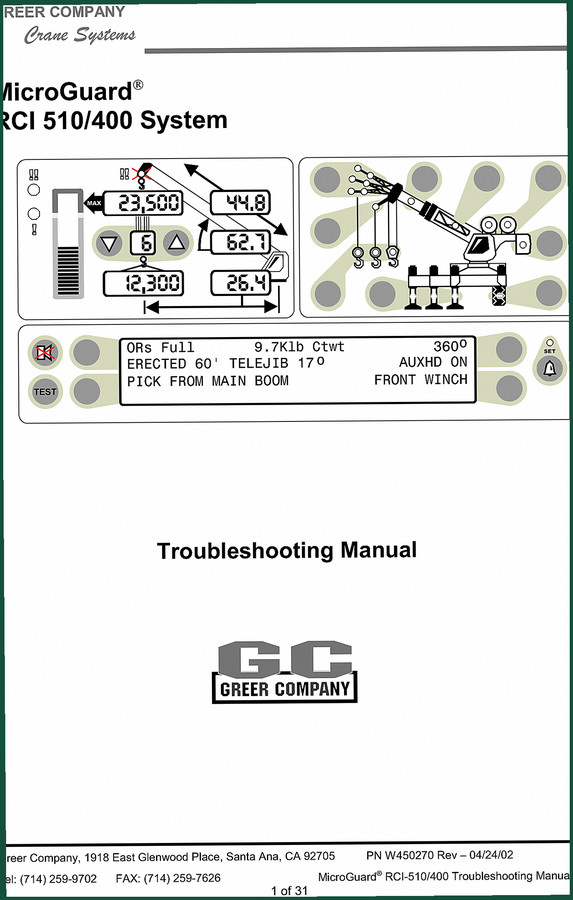
Greer RCI-510/400 2002 Troubleshooting Manual – OEM Diagnostics
Original price was: $39.90.$30.00Current price is: $30.00.
Factory troubleshooting manual for Greer RCI-510/400 crane system. 32 pages of diagnostic procedures, fault codes, pressure channel tests.
Description
Greer RCI-510/400 2002 Troubleshooting Manual
You’ve got a crane down in the yard, the display’s flashing some code you don’t recognize, and the rental compound is breathing down your neck. Reaching for a generic troubleshooting guide or some online forum thread is a fast track to replacing parts that weren’t broken in the first place. I’ve seen it a hundred times – wasted billable hours, customer waiting, and a pile of used pressure transducers on the bench. What you need is the original factory procedure, written by the engineers who built the MicroGuard system. This Greer RCI-510/400 2002 Troubleshooting Manual is exactly that – 32 pages of step-by-step diagnostic logic, fault code tables, and voltage test points that match the actual hardware on your crane. No aftermarket guesswork, no reprints of reprints.
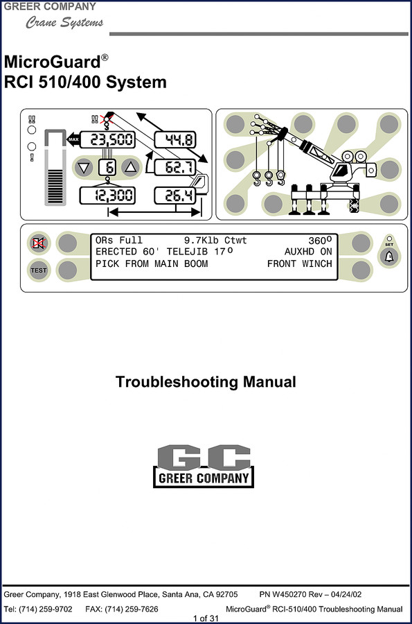
System Description and Fault Diagnostic Procedures
The manual opens with a full system description on page 3, giving you the architecture of the RCI-510/400 – the processor board, termination board, and how the pressure transducers, boom sensors, and swing potentiometer feed into the fault logic. Right after that, page 4 lays out the fault diagnostic procedure: start with visual checks, then power supply voltages, then pull fault codes. Follow that sequence and you won’t be chasing ghosts. For the exact charge pressure values and logic levels, you’ll be cross-referencing the voltage check table on page 7.
Greer RCI-510/400 Troubleshooting Manual – Fault Codes and Voltage Checks
Fault codes are listed on pages 5–6, covering everything from pressure channel faults to anti two-block errors. Each code comes with a description and a pointer to the specific test procedure. After you’ve pulled the code, you jump to the voltage checks section on page 7 to verify the power supply rails. This manual expects you to have a good multimeter and know how to back-probe a connector without shorting pins – if you don’t, this is the time to learn. The voltage table gives you nominal values for +5V, +12V, and the analog drive voltage. If those are off, you’re fixing a power supply problem, not a transducer.
Pressure Channel Fault Guide – Functional Tests for Transducers and Drive Voltage
Pages 10 through 13 cover the pressure transducers and analog drive voltage in detail. This is where the manual really shines – it walks you through a functional test of the pressure channel, step by step, including what readings to expect at the test points. If you’re familiar with the Mg313 system, there’s a note on page 13 for technicians who have that background, but don’t skip the earlier steps. The diagnostic approach here follows the same logic you’d use for a Manual Transmission diagnosis – systematic voltage checks before swapping parts. If you’ve worked on a Manual Transmission, you’ll appreciate how this manual organizes the steps.
Anti Two-Block System and Sensor Replacement
The anti two-block system has its own section starting on page 18, with logic level tables on page 19. If you’ve got a false two-block fault, the manual tells you exactly which pin to probe and what voltage range is acceptable. Sensor replacement procedures begin on page 20 for the pressure transducers, extension reel sensor, and boom angle sensor – all with torque specs for mounting bolts and connector orientation notes. Don’t try to swap those sensors without referencing the calibration notes; you’ll throw the system into fault.
Processor Board Layout and Chip Replacement
Pages 21 through 24 cover processor board replacement and chip removal. The layout diagram on page 24 shows every major component – Executive ROM, Personality ROM, Duty ROM, and the scratchpad RAM. If you’ve got a bad chip, the manual gives you the exact procedure for desoldering and reinstalling on page 23. Page 22 walks you through terminal board and box replacement. For earlier systems, check the Greer 424 2001 Troubleshooting Manual – OEM Factory Specs; for the non-/400 version of this model, use Greer RCI-510 2002 Troubleshooting Manual – OEM Factory Specs; and for the MicroGuard 404 system, grab Greer MicroGuard 404 Troubleshooting Manual.
Source Authenticity – This Is the Factory Print, Not a Copy
This file is a direct scan of the original Greer Company document, PN W450270 Rev – 04/24/02 – not a third-party rehash. The table of contents matches the printed manual, the page numbers line up, and the voltage tables haven’t been altered. Aftermarket manuals cut corners – they leave out the anti two-block logic levels or skip the processor board layout. You need the full picture when you’re troubleshooting a $500k crane. This manual gives it to you.
Frequently Asked Questions
- Does this manual cover the RCI-510/400 with all serial numbers?
- It covers the RCI-510/400 system as built by Greer through 2002. Serial number ranges are not listed, but the fault codes and voltage tables apply to any unit with the MicroGuard firmware from that era.
- What is the page count?
- 32 pages.
If you’re tired of chasing bad parts with no factory data, stop guessing. Access the Factory Manual now and get the diagnostic logic that Greer’s own technicians used in 2002.
Additional information
| Brand | Greer |
|---|---|
| Language | English |
4 reviews for Greer RCI-510/400 2002 Troubleshooting Manual – OEM Diagnostics
You may also like…
-
Sale!
Greer 424 2001 Troubleshooting Manual – OEM Fault Code Diagnostics
Original price was: $40.80.$30.00Current price is: $30.00. -
Sale!
Greer RCI-510 2002 Troubleshooting Manual – OEM Rated Capacity Limiter Diagnostics
Original price was: $43.80.$30.00Current price is: $30.00. -
Sale!

Greer 404 Troubleshooting Manual – OEM Fault Diagnostics for MicroGuard 404
Original price was: $54.80.$40.00Current price is: $40.00. -
Sale!

Greer MG500, RCI 510, MicroGuard 434, RCI 434, MG586 2002 Training Manual
Original price was: $48.00.$40.00Current price is: $40.00.
Related products
-
Sale!

1993 Operators Manual – International Bus 1000-3000 OEM Specs
Original price was: $12.30.$7.99Current price is: $7.99. -
Sale!
1991 Electrical Schematic – 112-Page OEM Wiring Diagram for International 1000-3000 Series
Original price was: $22.75.$17.50Current price is: $17.50. -
Sale!

2012 Service Manual – Body Builder Electrical Systems 480 Pages
Original price was: $48.28.$34.00Current price is: $34.00. -
Sale!

2006 Service Manual – International DT 466E, 530E Diesel Engine
Original price was: $67.50.$50.00Current price is: $50.00.
diy_master –
Perfect workshop guide. The file looks clean. Every torque spec is provided for Greer RCI510/400. I will definitely buy again.
Thomas B. –
I am extremely satisfied with this purchase. It is very easy to read on my phone without blur. A must-have for any Greer RCI510/400 DIYer doing repairs. Saved my repair job! Thank you.
Richard G. –
Excellent workshop guide. Immediate link after payment. It assisted me to repair my Greer RCI510/400 transmission. Saves me hundreds of dollars.
workshop_guy –
Perfect factory service manual. It is easily zoomable on my iPad without blur. Contains precise wiring diagrams for Greer. Great value for money.