
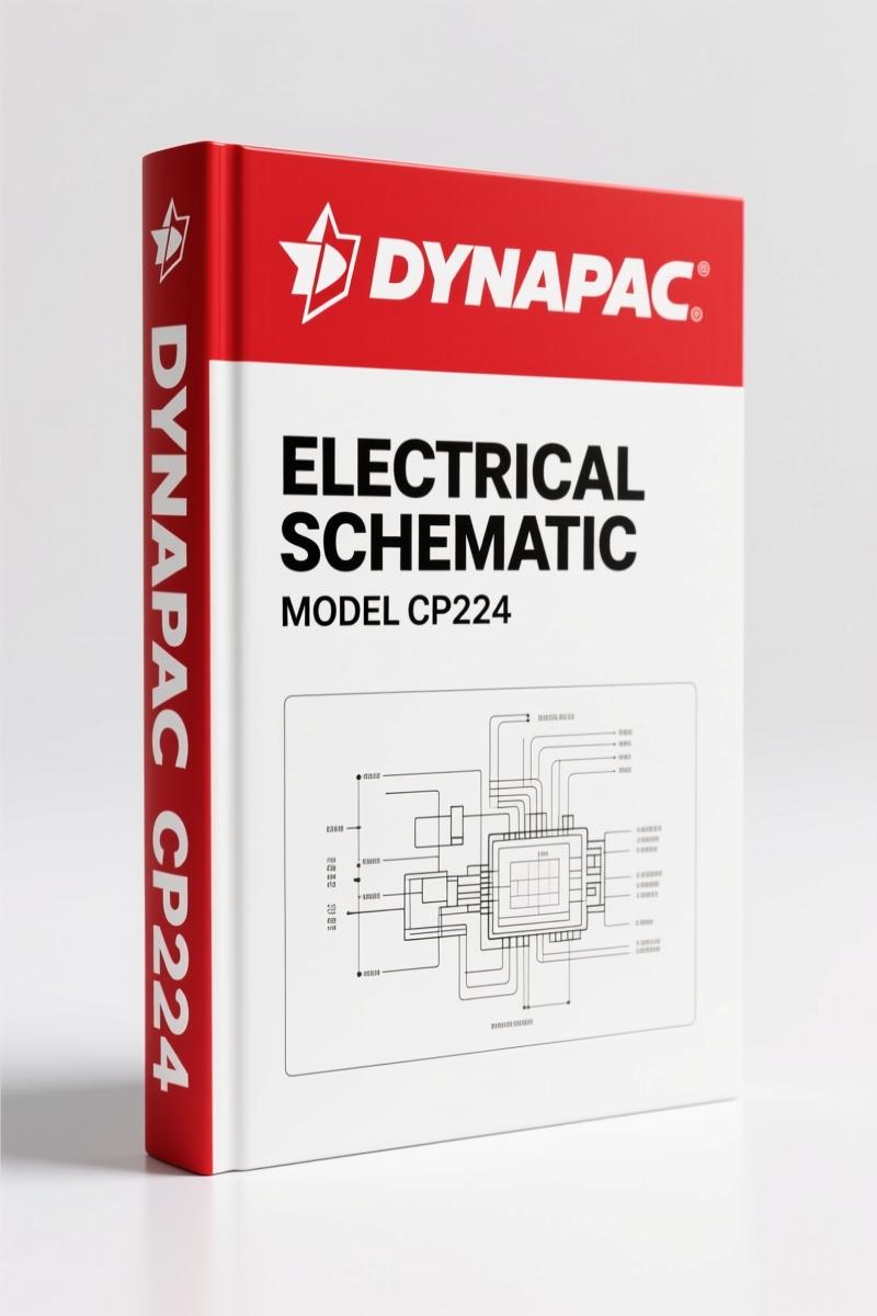
Dynapac CP224, CP274 Electrical Schematic – 73 Pages of Factory Wiring Data
Original price was: $32.50.$25.00Current price is: $25.00.
Factory electrical schematic for Dynapac CP224 and CP274. 73 pages covering CANBUS, ECM, ECU, lighting, and sprinkler circuits. OEM source.
Description
Electrical schematics from a third-party copy house will get you exactly where they should — lost, with a fried ECM and a billable hour wasted. If you’re working on a Dynapac CP224 or CP274 roller, you need the factory line drawings. I’ve seen too many guys try to trace a short using a blurry photocopy that skips half the connectors. That ends here. This set of 73 pages is the actual OEM Dynapac CP224, CP274 Electrical Schematic — the same diagrams the Dynapac techs pull up on their laptops. No redrawn garbage.
Page 2 of this document shows the ground wire connections at the left rear frame rail and the engine ground strap. X31 is the main ground point. Without that reference, you’ll be guessing which black wire is a ground and which is a shield. The manual labels every connector with an X prefix — X31, X5, X15 — so you know exactly where to put your meter leads.
ECM Diesel Engine: Where the Real Troubles Start
The ECM (engine control module) is the brain of this machine. Chapter 4 of the schematic, titled “ECM Diesel engine,” gives you every pin, every wire color, and every termination point. Page 5 details the CANBUS communication backbone with termination resistors R20, R21, and R22 — each 120 ohms. If you skip checking those resistors, you’ll be chasing a communication fault that doesn’t exist. The ECM power supply comes through the ECU Master (chapter 2), and if you miswire that, you’re buying a new controller. This manual shows the exact path: from master switch Q1 through fuse F10 (50A) and then to the ECU Master. Don’t bypass that circuit.
CANBUS Communication: Not a Phone Line
CANBUS is not something you can fix with a splice and some electrical tape. Chapter 1 covers the entire CANBUS communication layout. The twisted-pair wires are clearly marked, and the termination resistors at each node are specified. If the display unit loses communication with the engine, you go straight to the resistors and the connector X37. The schematic references coordinates like /5.B1 and /12.A1, so you can flip between pages without losing your place. Aftermarket diagrams often skip these cross-references. This one doesn’t.
ECU Master Power Supply and Standard Equipment
Chapters 2 and 3 deal with the ECU Master — power supply and standard equipment. On page 4 you see how the ignition switch S1 feeds power through fuse F1.1 (5A) to X15. The master switch Q1 routes battery power from the two 12V batteries (G1.1 and G1.2) through a 50A fuse to X30. If you have a no-crank or no-power condition, start at Q1 and work through these diagrams. The manual also covers the display unit, instrumentation control unit, and the buzzer (H10). Wire gauges are given in mm², like 903 1.50 for the battery positive to the master switch. Use the exact gauge when repairing.
Cab, Wiper/Washer, and Lights – Factory Routing
Chapters 8, 9, 11, 12, and 13 cover working lights, driving lights, horn, and the entire cab — wiper, washer, and cab power. These circuits are commonly hacked in the field. One wrong splice and you’ve got a fire. The OEM schematic shows wire colors like RD (red), BK (black), and numbers like 921 2.50 for the horn circuit. All connectors are labeled with X, so you can isolate the exact circuit. The lights have their own fuse paths; the manual shows the routing through the cab harness. This is how Dynapac engineers intended it to be wired.
Why OEM Beats Aftermarket for Electrical Schematics
Aftermarket wiring diagrams have killed more diag time than any bad sensor. They get wire colors wrong, skip ECM pinouts, and fudge the CANBUS termination. This document comes directly from Dynapac (part of the Atlas Copco Group). It’s a scanned OEM original, 73 pages of exactly what the factory trains its techs on. Every chapter — from CANBUS communication to Asphalttemp DCA-Asphalt — is present. If you need part numbers for connectors, pair this schematic with the Dynapac CP224 Parts Catalog – 562 Pages of OEM Specs or the Dynapac CP274 Parts Catalog – OEM Factory Part Numbers. For routine maintenance procedures, grab the Dynapac CP224 2010 User Manual – OEM Factory Specs for Roller Maintenance. And if you want a general overview of how these circuits work, check Automotive Wiring on Wikipedia.
FAQ – Common Questions on the Dynapac CP224/CP274 Electrical Schematic
- Does this manual cover both the CP224 and CP274 models?
- Yes. The title says CP224/CP274 and the diagrams apply to both. The ground wiring on page 2 is specific to the CP274 but the electrical architecture is identical between models.
- What type of file is this?
- It’s a PDF, 73 pages, scanned from the original OEM document. You get the exact same diagrams as the factory service network.
- Are the wire colors printed accurately?
- Yes. The PDF shows color codes like RD (red), BK (black), and numbers like 903 1.50 which denote wire gauge in mm². If you need to splice, use the exact gauge listed.
- Can I use this to diagnose a no-start on a CP274?
- Absolutely. Start with the ECU Master Power supply chapter. Check the master switch Q1 and fuse F10 on page 4. Then trace the ignition switch S1 and X15. The ECM Diesel engine chapter shows the ECM pinout. The CANBUS communication chapter on page 5 shows the termination resistors. This manual eliminates guesswork. You will save hours of diag time and avoid replacing parts that were never broken.
Don’t pay a dealership three hours of labor to chase a wire that’s shown on one page of this book. You have the tool — the right tool is the factory diagram. Access the Factory Manual now and keep it on your tablet in the cab.
Additional information
| Brand | Dynapac |
|---|---|
| Language | English |
3 reviews for Dynapac CP224, CP274 Electrical Schematic – 73 Pages of Factory Wiring Data
You may also like…
-
Sale!
Dynapac CA-15A 1987 Parts Catalog – OEM Exploded Views
Original price was: $89.70.$65.00Current price is: $65.00. -
Sale!
Dynapac CA250 CA280 CA300 CA260 Workshop Manual – 42 Pages
Original price was: $88.40.$65.00Current price is: $65.00. -
Sale!
Dynapac CA 25, CA 25D, CA 25PD, CA 25R Parts Catalog – OEM Spare Parts (322 Pages)
Original price was: $83.85.$65.00Current price is: $65.00. -
Sale!
Dynapac CC 41 Parts Catalog – 242 Pages OEM Exploded Views
Original price was: $80.60.$65.00Current price is: $65.00.
Related products
-
Sale!

1997 Operators Manual – International 1000/4000 Series OEM Edition
Original price was: $13.49.$9.99Current price is: $9.99. -
Sale!

Technical Manual – International DT 530 & HT 530 (118 Pages)
Original price was: $37.00.$25.00Current price is: $25.00. -
Sale!

2004 Acura TSX Wiring Diagram – 73-Page Factory Electrical Schematics
Original price was: $15.88.$9.99Current price is: $9.99. -
Sale!
International 1000-3000 Series Operators Manual – 132 Pages of OEM Specs
Original price was: $14.40.$10.99Current price is: $10.99.
gearhead88 –
Excellent quality! The pages are clean and well indexed. Every torque spec is provided for Dynapac CP224,. Saved my repair job! Thanks.
Charles W. –
I am so happy with this purchase. The PDF looks clean. It helped me to rebuild my Dynapac CP224, electrical system. Saved my repair job! Thanks.
diy_master –
Five stars! The scan is high-quality and well indexed. Contains clear bolt torque specs for Dynapac. Worth every penny.