
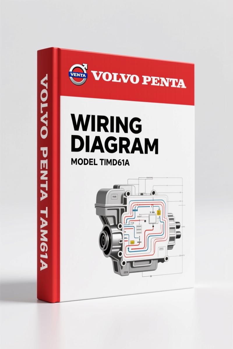
Volvo Penta TAMD61A, TAMD62A, TAMD63L-A, TAMD63P-A, TAMD71A Wiring Diagram – 52 Pages of Factory Electrical Schematics
Original price was: $45.30.$30.00Current price is: $30.00.
Factory wiring diagrams for Volvo Penta TAMD61A-TAMD71A marine engines. 52 pages with EDC control system, instrument panel, and water jet wiring.
Description
Volvo Penta TAMD61A, TAMD62A, TAMD63L-A, TAMD63P-A, TAMD71A Wiring Diagram
If you’ve ever spent an afternoon tracing a no-start on a Volvo Penta TAMD61A or TAMD71A because the aftermarket diagram had the wrong pinout, you’ll appreciate this. This is the factory wiring diagram – the one the techs at Volvo Penta used when these engines were new. 52 pages, no guesswork, no photocopied garbage. Every engine variant from the TAMD62A to the TAMD63P-A and TAMD71A is covered, split by voltage (12V and 24V) and by control system. I’ve torqued enough head bolts to know that electrical gremlins are what sink boat repairs. This book fixes that.
What This Wiring Diagram Covers (Engine-Specific Layouts)
Pages 7 through 19 break down the Wiring Diagrams, engine section by exact model. Need the starting circuit for a TAMD63L-A 24V system? Page 9. Running a TAMD71A with a 12V harness? Page 7. The manual also includes the TAMD62A, TAMD63P-A, and all the TAMD71 variants – even the water-jet models like TAMD72WJ-A. Each diagram is reproduced from the original Volvo Penta engineering prints. No redrawing, no interpretation. Wire colors, connector pin numbers, fuse ratings – it’s all there just as it came off the factory floor.
Instrument Panel and Flying Bridge Wiring (Pages 20–28)
Marine installations never have just one control station. This section covers the main control position instrument panel (page 22), the alternative control position (flying bridge, page 24), and the instrument kits for both. Page 26 walks you through the instrument kit wiring for the main station – essential if you’re retrofitting gauges or chasing a flickering tach. The block diagram on page 20 gives you a system overview before you dive into the specific schematics. If you’ve ever wired a flying bridge without factory documentation, you know how easy it is to cross a sender wire. This eliminates that risk.
EDC Control System: Factory Color Coding and Diagnostics
Pages 30–38 are where this manual earns its keep. The Wiring diagrams – control system (EDC) section shows the full Electronic Diesel Control harness – sensors, actuators, ECU connections. Page 38 is the Wiring diagram – EDC colour coding. That page alone has saved me hours on a boat with intermittent limp-home mode. You get the color codes for every wire in the EDC harness, plus the alternative control system wiring (page 40) for dual-station EDC setups. Do not attempt EDC diagnostics without this – aftermarket diagrams rarely get the shielded-ground routing right, and that causes phantom fault codes.
Water Jet and Additional Systems
If your boat runs a water-jet drive, pages 44 and 46 are critical. The Wiring diagram – water jet control panel (page 44) shows the joystick and actuator wiring. The Reversing bucket operation – water jet (page 46) covers the solenoid and limit-switch circuits. Both pages are tied directly to the engine wiring block, so you can chase a non-responsive bucket from the helm all the way back to the ECU. Other sections include references to Service Bulletins (page 48) – important for checking ECM firmware updates and wiring revisions.
3 Reasons to Choose This OEM Wiring Diagram
First, it’s factory – no third-party reprints. Volvo Penta sealed this document with their engineering stamps. Second, it includes both 12V and 24V variants for every model listed. Third, the 52 pages cover more than just the engine harness: instrument panels, flying bridge, EDC, water jet – you get the complete electrical system. The aftermarket PDFs I’ve seen often omit the alternative control position wiring or the EDC color key. This one doesn’t.
Who Needs This Wiring Diagram
If you work on marine diesels for a living or maintain your own boat with a TAMD-series engine, this is the electrical bible for that powerplant. DIYers who have pulled a harness apart and need to re-pin connectors will find the exact factory assignments. Marine mechanics will use it for EDC diagnostics and flying bridge installations. The manual assumes you know how to read a schematic – it doesn’t hold your hand, but it gives you the real data. Pair it with the full workshop manual for torque specs and repair procedures: check the Volvo Penta TAMD61-TAMD72 Workshop Manual. For other Volvo Penta electrical needs, see the Volvo Penta FE 2009 Wiring Diagram – Factory OEM Manual and the Volvo Penta EC140B Wiring Diagram – 19-Page Factory Manual.
Why Factory OEM Wiring Over Aftermarket?
I’ve seen aftermarket wiring diagrams that swap the alternator sense wire color because someone scanned a faded copy. On a marine engine, a misrouted sense wire can cause overcharging and battery explosions. Volvo Penta does not make those mistakes. Every wire gauge, every connector terminal, every ground point in this manual was verified during engine production. If you want background on how automotive wiring standards evolved, Automotive Wiring on Wikipedia covers the basics. For marine-specific practices, Automotive Wiring (same article) has a section on corrosion protection – but read the manual first.
Frequently Asked Questions
- Does this wiring diagram cover both 12V and 24V systems?
- Yes. Each engine model has separate diagrams for 12V and 24V electrical systems, clearly labeled in the table of contents and on each page.
- Is the EDC color coding included?
- Page 38 is dedicated to EDC colour coding. It shows every wire in the EDC harness by function and color, including connector pin numbers.
- Does it include instrument panel wiring for dual stations?
- Pages 22 through 28 cover the main control position, alternative control position (flying bridge), and auxiliary control panel. Wiring for instrument kits at both stations is included.
- Will this help me troubleshoot a water-jet reversing bucket that won’t engage?
- Pages 44 and 46 cover the water jet control panel and reversing bucket operation. You get the solenoid circuits, limit switches, and actuator wiring – enough to trace the fault from helm to pump.
This manual is a direct access – no shipping, no waiting. It’s the same PDF Volvo Penta dealers use. If you’ve got a TAMD61A, TAMD62A, TAMD63L-A, TAMD63P-A, or TAMD71A in your engine room, you need this on your laptop. Access the Factory Manual while the link is live – I’ve seen OEM documents get pulled when newer models come out. Don’t get caught tracing wires with a multimeter and a guess.
Additional information
| Brand | Volvo Penta |
|---|---|
| Language | English |
4 reviews for Volvo Penta TAMD61A, TAMD62A, TAMD63L-A, TAMD63P-A, TAMD71A Wiring Diagram – 52 Pages of Factory Electrical Schematics
You may also like…
-
Sale!
Volvo Penta D12A, D6B, D12C Technical Manual – 23-Page Factory Abbreviation Reference
Original price was: $67.50.$50.00Current price is: $50.00. -
Sale!
Volvo Penta B7, B9, B12 2007 Wiring Diagram – Factory Electrical Schematics
Original price was: $71.10.$45.00Current price is: $45.00. -
Sale!
Volvo Penta FH, FM Technical Manual – Factory Specifications for Suspension & Emissions
Original price was: $79.00.$50.00Current price is: $50.00. -
Sale!

Volvo Penta TD520GE, TAD520GE, TD520VE, TD420VE, TAD420VE 2007 Workshop Manual
Original price was: $64.00.$50.00Current price is: $50.00.
Related products
-
Sale!

1994 Troubleshooting Manual – International 1000-4000 FBC
Original price was: $60.00.$50.00Current price is: $50.00. -
Sale!

2004 Acura TSX Wiring Diagram – 73-Page Factory Electrical Schematics
Original price was: $15.88.$9.99Current price is: $9.99. -
Sale!
International 1000-3000 Series Operators Manual – 132 Pages of OEM Specs
Original price was: $14.40.$10.99Current price is: $10.99. -
Sale!

2011 Parts Catalog – International Truck OE Parts Documentation (1786 Pages)
Original price was: $34.50.$25.00Current price is: $25.00.
James L. –
Great buy! It is easily zoomable on my tablet without losing quality. A must-have for any Volvo Penta Penta DIYer doing repairs. Saved my repair job! Thank you.
pro_mechanic –
I am extremely satisfied with this transaction. The scan is high-quality and well indexed. Every torque spec is provided for Volvo Penta Penta. Saves me hundreds of money.
Richard G. –
Five stars! The file is high resolution. It helped me to repair my Volvo Penta Penta electrical system. I will recommend this shop to others.
David K. –
I am extremely satisfied with this transaction. The text is searchable and easy to navigate. It assisted me to fix my Volvo Penta Penta transmission. Highly recommended for mechanics.