
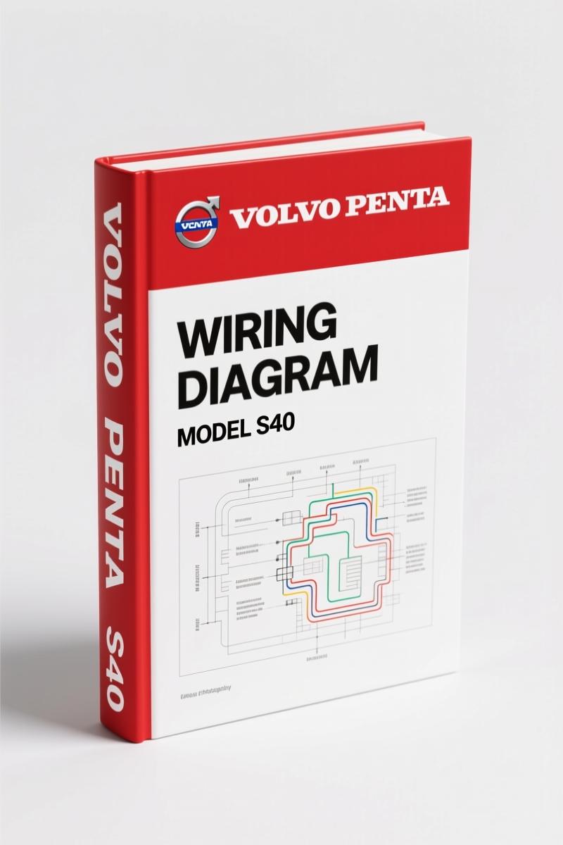
Volvo Penta S40, V50, C70 2007 Wiring Diagram – Factory Electrical Schematics
Original price was: $39.50.$25.00Current price is: $25.00.
Factory 324-page wiring diagram for Volvo Penta S40, V50, C70 (2007). Covers SRS, CAN, engine management, fuses, and relays.
Description
Volvo Penta S40, V50, C70 2007 Wiring Diagram
If you have ever leaned over a fender with a cheap aftermarket wiring diagram that shows a brown wire as ground when it is actually a switched 12V, you already know the cost of guessing. Hours wasted, modules fried, and an airbag light that refuses to go out. This is the genuine Volvo Penta S40, V50, C70 2007 Wiring Diagram – factory publication TPu202f3999202 straight from Volvo. 324 pages of OEM electrical documentation that covers every connector, fuse, relay, and ground point for these Volvo models. No reprints, no interpretation, no third-party errors. This is what the factory technicians used.
SRS/Airbag Safety: Page 2 Warning You Cannot Ignore
Page 2 of this manual carries a bold warning about SRS, SIPS bag, and Inflatable Curtain (IC) systems. Working on a car with live airbags means one wrong move can cost you a deployment. The diagram shows you exactly which circuits are tied to the SRS module, how the steering column clock spring routes wires, and where the impact sensors sit. You get the factory recommendations: never pinch wires near the A‑pillar, never install accessories near sensor zones, and always ground certain components before powering up. If you are pulling a dash or replacing a seat, you need this wiring data before you disconnect anything.
What’s Inside: 324 Pages of OEM Electrical Data
Every major electrical system in the 2007 S40, V50, and C70 is broken down by group. After the abbreviations and instructions on how to read the diagrams (yes, there is a specific method), the manual moves through:
- Fuses – engine compartment distribution box F1‑F34, Central Electronic Module (CEM) F43‑F86, battery PF1‑PF2.
- Relays – ignition switch relays, distribution box R2‑R14, CEM relays R1‑R18, plus a section for “Other relays”.
- Ground connections – 31/3 through 31/117, including chassis grounds.
- Control modules – location overview, pin‑out for CEM (2 pages), data communication for Low/High CAN, MOST (separate for S40/V50 and C70), and LIN bus.
- Groupu202f23 Fuel system – engine management for diesel 5‑cyl 2.4u202fL, gas 4‑cyl 1.6u202fL, 1.8u202fL, 2.0u202fL, 5‑cyl, 5‑cyl turbo, and diesel 4‑cyl 1.6u202fL & 2.0u202fL. Emission control schematics included.
- Groupu202f26 Cooling system – cooling fan wiring for gas and diesel.
- Groupu202f27 Engine control – cruise control for 4‑cyl and 5‑cyl.
- Groupu202f32 Alternator & voltage regulator – power supply diagrams for 4‑cyl and 5‑cyl.
- Groupu202f33 Starting system – starting circuits for 4‑cyl, 5‑cyl, and 5‑cyl diesel.
- Groupu202f35 Lighting – follow‑me‑home, high/low beam (including Bi‑Xenon with automatic beam length adjustment), parking lights, fog lights, brake lights, reversing lights, interior lighting for S40/V50 and C70, and instrument illumination.
- Groupu202f36 Additional electrical equipment – direction indicators, hazard flashers, windshield wiper/washer, headlight washer, rear wiper (V50), rain sensor, horn, immobilizer/steering column lock, keyless vehicle for S40/V50 and C70.
Each section is laid out with wire colors, component locations, and connector pin numbers. You are not guessing which wire is which.
Group 23 Fuel System: Diesel and Gasoline Engine Wiring
This is the section that saves you when a no‑start condition is caused by a broken wire to the fuel injector driver. The diagrams cover engine management for almost every engine offered in these cars: 4‑cylinder 1.6u202fL, 1.8u202fL, 2.0u202fL, 5‑cylinder naturally aspirated and turbo, plus the 2.4u202fL diesel (5‑cyl) and 1.6u202fL / 2.0u202fL diesel (4‑cyl). Emission control systems are also diagrammed. If you are swapping an engine or chasing a misfire, this group gives you the factory signal paths from the ECM to each injector and sensor.
Using the Manual with Your Multimeter and Test Light
Open the “Explanations” section first. It shows you the abbreviations Volvo uses (e.g., CEM, SCU, AEM) and how to follow a circuit that spans multiple pages. The “Electrical distribution” pages map the power flow from the battery through fuses and relays to each subsystem. Ground connection tables list every ground point by location and splice number – this alone can save you hours of probing random chassis bolts. For example, ground 31/80 is at the left rear of the engine compartment. When you have a dead tail light, start by checking that ground. No other manual gives you that level of detail.
Why Aftermarket Diagrams Fail and This One Doesn’t
Aftermarket wiring books often reuse diagrams from earlier model years, shuffle wire colors, or omit crucial connectors like the Bi‑Xenon auto‑leveling module. This manual is an official Volvo publication dated 2007, with revisions up to Aprilu202f2006 noted. It is the same document used by dealership technicians. If a circuit changed for the 2008 model year, that is not in here – and the manual tells you to check service bulletins for later updates. That is honest engineering documentation, not a generic collection of sketches.
- Does this wiring diagram include torque specs for engine bolts?
- No. This is a wiring diagram, not a repair manual. It covers electrical circuits, fuses, relays, and control modules. For torque specs you need the factory service manual.
- Will this manual work for my 2008 Volvo C70?
- Only if your car was built before Aprilu202f2006. The manual states that changes after that date are not included. Check your vehicle production date on the door sticker. Later models may need a supplement or updated EWD.
- Is this a printed book or a downloadable PDF?
- This is a digital PDF format. You receive the full 324‑page document exactly as scanned from the original factory publication. No watermarks, no missing pages.
- How is this different from a Haynes or Chilton manual?
- Haynes redraws diagrams and often combines multiple model years into one generic schematic. This is the actual factory wiring diagram with the exact wire colors, connector views, and ground locations Volvo engineered. If you need to trace a CAN bus signal or identify the correct fuse for the SIPS bag, this is the only source that matches the car’s harness.
You have spent good money on a Volvo. Do not troubleshoot its electrical system with a photocopy of a copy. Access the Factory Manual from AutoRepairManuals and get the genuine OEM wiring data for your 2007 S40, V50, or C70. Related manuals you might need:
- VOLVO C30 S40 V50 C70 Wiring Diagram Supplement
- Volvo 850 1995 Repair Manual
- VOLVO C30 S40 V50 C70 2011 Wiring Diagram – Section: Running/Par
For more background on automotive wiring standards, see Automotive Wiring on Wikipedia and Automotive Wiring resources.
Additional information
| Brand | Volvo Penta |
|---|---|
| Language | English |
4 reviews for Volvo Penta S40, V50, C70 2007 Wiring Diagram – Factory Electrical Schematics
You may also like…
-
Sale!
Volvo Penta FH, FM Technical Manual – Factory Specifications for Suspension & Emissions
Original price was: $79.00.$50.00Current price is: $50.00. -
Sale!
Volvo Penta TD520GE, TAD520GE, TD520VE, TD420VE, TAD420VE 2007 Workshop Manual
Original price was: $64.00.$50.00Current price is: $50.00. -
Sale!
Volvo Penta B7, B9, B12 2007 Wiring Diagram – Factory Electrical Schematics
Original price was: $71.10.$45.00Current price is: $45.00. -
Sale!
Volvo Penta D12A, D6B, D12C Technical Manual – 23-Page Factory Abbreviation Reference
Original price was: $67.50.$50.00Current price is: $50.00.
Related products
-
Sale!

Technical Manual – International DT 530 & HT 530 (118 Pages)
Original price was: $37.00.$25.00Current price is: $25.00. -
Sale!

1995 Operators Manual – International 1000-4000 Series | OEM Documentation
Original price was: $12.49.$9.99Current price is: $9.99. -
Sale!

Acura Integra 1998 Service Manual – 1891 Pages Factory OEM Documentation
Original price was: $31.75.$25.00Current price is: $25.00. -
Sale!

1991 Operators Manual – International Truck OEM Specs (108 Pages)
Original price was: $13.63.$10.99Current price is: $10.99.
gearhead88 –
I am very pleased with this purchase. The PDF quality is excellent. Every spec sheet is provided for Volvo Penta Penta. Saves me a lot of dollars.
workshop_guy –
Excellent quality! The file is high resolution. Contains detailed wiring diagrams for Volvo Penta. Saved my repair job! Thank you.
David K. –
Excellent quality! It is very easy to read on my phone without losing quality. Contains detailed bolt torque specs for Volvo Penta. Saved my repair job! Thanks.
James L. –
Highly recommended! The scan is high-quality and well indexed. Every torque spec is provided for Volvo Penta Penta. Saves me a lot of time.