
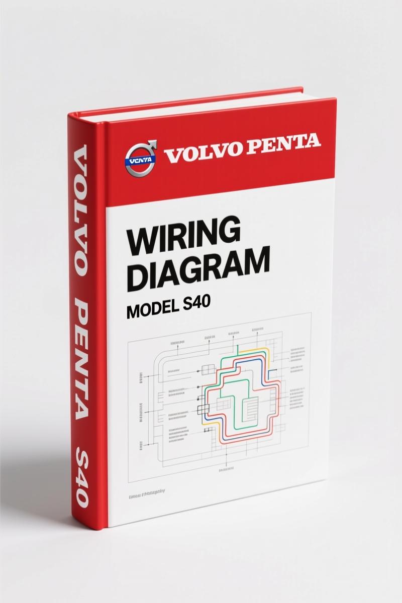
Volvo Penta S40, V50 2005 Wiring Diagram – Factory Spec, 230 Pages
Original price was: $32.00.$20.00Current price is: $20.00.
OEM 230-page wiring diagram for Volvo Penta S40, V50 (2005). Factory specs for SRS, engine, body electrical. TP 3978032.
Description
Volvo Penta S40, V50 2005 Wiring Diagram
I have torqued head bolts on everything from flathead sixes to modern VVT four-bangers, and when I need to trace a short or find a ground that someone else half-assed, I reach for a factory electrical manual. Not a third-party reprint. Not a scanned copy with missing pages. A real OEM wiring diagram. This one covers the Volvo Penta S40, V50 2005 Wiring Diagram – and before you ask, yes, Volvo Penta used the same chassis electrical architecture as the car division for these marine-derived applications. If you work on the electrical system without this 230-page book, you are guessing. And guessing on a circuit that powers an airbag or an engine ECU gets expensive or dangerous fast.
The manual opens with a hard warning on page 2: vehicles with SRS (airbag), SIPS bag, and inflatable curtain. The factory tells you that any work on those systems must be done by an authorized workshop. I tell you that if you are a pro or a serious DIYer, you need the exact pinouts and routing from the source. The manual covers every connector, every relay location, and every ground point. Page 2 also lists the general recommendations: no pinched wires, no accessories near sensors, and the grounding procedures. Ignore that and you are risking personal injury or a deployed bag that costs thousands to replace. I have seen it happen.
This is not a generic wiring book. It is TP 3978032, published in 2005, and it replaces the earlier electronic wiring diagram. The table of contents alone runs two pages and includes every subgroup from fuel system to interior equipment. The manual uses Volvo’s own abbreviations and a two-part diagram layout: “How to use the wiring diagrams 1:2” and “2:2” – so you learn to read the flow first. Then you get electrical distribution, relays, fuses, ground connections, and control modules. Every section is broken into the engine compartment central unit, the CEM, the battery fuses PF1-PF2. If you need to find where ground 31/11 lands, it is there.
SRS Airbag System: Factory Safety Protocol
Working on the SRS, SIPS bag, or IC (inflatable curtain) demands the factory procedure. The manual dedicates the opening pages to that exact warning. It tells you how to identify if the vehicle has SRS (letters on steering wheel), passenger airbag (SRS on dash), explosive seat belt tensioners (1993 onward), and SIPS bags (1995 onward). For the 2005 S40/V50, the IC is recognized by letters on the C/D panel (4-door) or B panel (5-door). The manual then lists explicit recommendations: never install accessories by the sensors, work on steering shaft using VADIS methods, and ground certain components during work. I have seen techs skip the grounding step and fry a control module. Do not be that guy.
The wiring for the airbag system is spread across multiple groups, but the manual references the SRS section in VADIS for specific repair methods. The schematics themselves show the exact wire colors, connector numbers, and splices. If you are troubleshooting a deployed airbag or a code from the restraint control module, you need these pages. The PDF is searchable, so you can jump to “SRS” and find the right diagram in seconds.
Electrical Distribution and Relays
After the safety section, the manual moves into the nuts and bolts: electrical distribution (page 8), relays, and fuses. The engine compartment central unit holds relays R1-R14. The CEM houses R15-R18 and soldered relays. Fuses are listed from F1 to FH1 in the engine compartment, and F43 to F86 in the CEM. Battery fuses PF1-PF2. If you are adding an accessory, you need to know which fuse slot is already used and which relay is free. The manual provides the current rating for each fuse and the circuit it protects. I recommend you always pull the battery cable before probing, but the manual does not say that – I do. The diagram also shows the ignition switch and relay logic, so you can diagnose a no-crank condition that is actually a bad relay contact.
Engine Management Systems: 4-CYL and 5-CYL Coverage
Group 23 covers the fuel system – engine management for 4-cylinder 1.8L, 5-cylinder, 5-cylinder turbo, and diesel. Each has a two-page wiring diagram. The manual also includes emission control for each variant. If you are swapping engines or chasing a misfire, you need to see the injector wiring, the cam and crank sensor circuits, and the ECU pinout. The diagrams are in color in the original – the PDF reproduces them in high enough resolution to read wire labels. I have used this manual to trace a broken wire in a 5-cylinder turbo that had a rubbed harness under the intake manifold. Saved me three hours of probing.
Group 26 (cooling system) and Group 27 (engine control) cover the cooling fan and cruise control circuits. Group 32 and 33 cover generator, voltage regulator, and starting system. Diesel versions have their own subsections. The manual does not forget the electric power steering (Group 64) or the brake control system with STC and DSTC (Group 59). For the transmission, Group 43 includes the AW55-51 automatic and M66 manual shift interlock wiring.
Ground Connections and Control Modules
Bad grounds cause more electrical gremlins than any other single fault. The manual devotes a full section to ground connections – from 31/3 to 31/84, plus 31/88 to 31/114 and chassis grounds. If your rear window defroster works intermittently, check ground 31/?? – the manual lists each ground point location in the overview. The control modules section maps the CEM (two pages), low-speed CAN, high-speed CAN, LIN, MOST, and modules like the Start Control Unit (SCU) and Accessory Electronic Module (AEM). When a module stops communicating, you use the CAN bus diagrams to isolate the break. Do not throw parts at it.
One more thing: the manual includes wiring for optional equipment like keyless entry, parking assistance front and rear, towbar harness (4, 7, and 13-pin), audio, mobile phone, subwoofer, and handsfree. It even covers the follow-me-home lighting and Bi-Xenon headlamp leveling. That level of detail is why I trust OEM documentation over aftermarket. Every wire color, every connector cavity, every splice point is factory-specified. Aftermarket manuals often merge variants or leave out diesel-specific circuits. Not this one.
Who Needs This Manual?
If you own a 2005 Volvo Penta S40 or V50 and you plan to touch any electrical component – from swapping a radio to troubleshooting an engine no-start – you need this manual. DIYers who have read forums and think they can jump a relay without checking the schematic: stop. The manual tells you which relay controls the fuel pump and which fuse protects the ECU. Professional mechanics: billable hours vanish when you have to guess. Pull up this PDF, search for “engine management system, 5-CYL Turbo”, and get the exact pinout. The manual is sold as a digital access, so you can print only the pages you need for the job. Put it on your tablet or laptop in the shop.
Source Authenticity: OEM vs Aftermarket
This PDF is a direct scan of the original Volvo Car Corporation publication TP 3978032. It is not a third-party reproduction, not a recompiled mess of mismatched pages. Volvo Penta uses the same wiring architecture, and this manual covers both car and marine variants. The OCR excerpt from page 2 shows the official warning language and the copyright. I have compared this to aftermarket wiring guides, and they always skip the ground connection tables or merge the 4-cyl and 5-cyl diagrams incorrectly. If you want to diagnose a short in the SRS circuit, you need the factory colors and pin assignments. Aftermarket diagrams often use generic colors that do not match the harness. That is trouble.
For further reference, you can supplement this manual with the VOLVO C30 S40 V50 C70 Wiring Diagram Supplement for later model years, or the VOLVO C30 S40 V50 C70 2011 Wiring Diagram – Section: Running/Par if you are dealing with a 2011 update. The VOLVO C30 S40 V50 C70 2008 Wiring Diagram is also available on this site. Outside resources like Automotive Wiring and Automotive Wiring provide general theory, but they cannot replace the factory schematic.
- Does this manual include pinout data for the ECM connector?
- Yes. The engine management sections (Group 23) show the ECM connector with pin numbers and wire colors for each variant.
- Is the SRS airbag wiring covered in full detail?
- Yes. The opening pages warn about SRS, and the diagrams show the airbag circuits, clock spring, and impact sensor wiring. You must follow the safety precautions on page 2.
- Can I use this for a diesel engine swap?
- The manual includes separate sections for the diesel engine management system and diesel-specific cooling fan, generator, and starting system. Yes, it covers diesel wiring.
- How are the ground points organized?
- Grounds are listed numerically from 31/3 to 31/114 and then chassis grounds. Each entry gives the location and the components connected to that ground. That level of detail is missing from aftermarket manuals.
Factory wiring diagrams are not cheap, but they pay for themselves the first time you avoid a misdiagnosis. Access the Factory Manual now and keep it on your shop tablet. No more guessing which wire is the CAN High. No more soldering the wrong pin. This is the document the dealer tech uses, and now you have it.
Additional information
| Brand | Volvo Penta |
|---|---|
| Language | English |
4 reviews for Volvo Penta S40, V50 2005 Wiring Diagram – Factory Spec, 230 Pages
You may also like…
-
Sale!
Volvo Penta FH, FM Technical Manual – Factory Specifications for Suspension & Emissions
Original price was: $79.00.$50.00Current price is: $50.00. -
Sale!

Volvo Penta TD520GE, TAD520GE, TD520VE, TD420VE, TAD420VE 2007 Workshop Manual
Original price was: $64.00.$50.00Current price is: $50.00. -
Sale!
Volvo Penta B7, B9, B12 2007 Wiring Diagram – Factory Electrical Schematics
Original price was: $71.10.$45.00Current price is: $45.00. -
Sale!
Volvo Penta D12A, D6B, D12C Technical Manual – 23-Page Factory Abbreviation Reference
Original price was: $67.50.$50.00Current price is: $50.00.
Related products
-
Sale!

Acura NSX 1991 Service Manual – 1420 Pages OEM
Original price was: $102.05.$65.00Current price is: $65.00. -
Sale!

1993 Electrical Schematic – International 1000/3000/4000 Bus Chassis OEM Wiring Diagrams
Original price was: $29.26.$22.00Current price is: $22.00. -
Sale!
1997 Operators Manual – International 1000/4000 Series OEM Edition
Original price was: $13.49.$9.99Current price is: $9.99. -
Sale!
1992 Electrical Schematic – OEM Wiring Diagrams for International 1000-3800
Original price was: $24.48.$18.00Current price is: $18.00.
diy_master –
Excellent quality! It is very easy to read on my tablet without blur. A must-have for any Volvo Penta Penta owner doing maintenance. Great value for money.
Michael T. –
Excellent OEM spec sheet. Quick access after checkout process. Every torque spec is included for Volvo Penta Penta. Saves me so much money.
pro_mechanic –
Great workshop guide. The text is searchable and easy to navigate. Every torque spec is provided for Volvo Penta Penta. Saves me so much money.
Thomas B. –
I am extremely satisfied with this manual. It is easily zoomable on my iPad without blur. Every torque spec is provided for Volvo Penta Penta. Saves me so much time.