
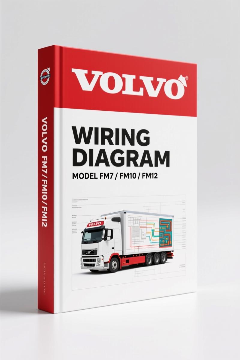
Volvo Penta FM12, FM7, FM10 Wiring Diagram – Factory Electrical Schematics
Original price was: $35.00.$25.00Current price is: $25.00.
Factory wiring diagram for Volvo Penta FM12, FM7, FM10. 152 pages of component schematics, fuse/relay locations, and connector lists.
Description
Volvo Penta FM12, FM7, FM10 Wiring Diagram – 152-Page OEM Factory Manual
Every time I see a tech tracing a short with a cheap aftermarket wiring diagram, I want to walk over and hand them a proper factory manual. You are trying to fix a Volvo Penta FM12, FM7, or FM10, and you are staring at a bundle of wires that all look the same. The difference between a two-hour diagnosis and a two-day headache is found in the Volvo Penta FM12, FM7, FM10 Wiring Diagram—152 pages of OEM factory wiring that tells you exactly where every pin goes, what color the wire is, and which fuse feeds it. This is the same document Volvo Truck Corporation issued under order number TSP127085.
Component Wiring Diagrams: The Core of This 152-Page Manual
Starts with a sample wiring diagram and symbol legend on pages 2-3. Then the component wiring diagram index on page 5, followed by the actual component wiring diagrams starting on page 7. You get the circuit card electrical centre layout on page 125, fuses on page 126, relays on page 127. That is not guesswork—that is the factory layout as Volvo designed it. Each diagram shows wire colors, connector views, and device pin numbers. You do not have to cross-reference three different aftermarket sources to figure out if a wire is a ground or a signal.
Where Do You Find the Fuse and Relay Layout?
Page 126 lists every fuse on the circuit card electrical centre. Page 127 gives you the relays. If you are chasing a no-start on a FM10, you check fuse F7 first—the manual tells you which circuit that fuse protects. You do not waste time pulling fuses randomly. The relay section shows coil and contact pinouts, so you can test the relay before you replace it. That saves parts money and downtime.
Cable Colour Code: Decoding the Wires
Page 147 has the cable colour code. Yellow is typically ignition-switched, red is battery positive, black is ground—but Volvo uses their own abbreviations like SB (black), SR (blue), OR (orange). The manual lists them all. Do not assume colors match a generic standard; check the code before you splice. A wrong assumption here can send 12 volts into a sensor ground—fried ECU.
3 Reasons Factory Wiring Diagrams Beat Aftermarket Copies
First, the component list on page 140 gives you the Volvo part numbers for every sensor, solenoid, and control unit. Second, the connector list on page 132 has the cavity numbers—aftermarket diagrams often leave those out. Most aftermarket versions also shrink the diagrams so you cannot read the pin numbers. Third, the illustrations section from page 58 shows physical locations of connectors and grounds. You cannot get that from a third-party PDF that someone scanned from a scan. For other Volvo truck models, check VOLVO FM9 FM12 FH12 Wiring Diagram if you have an FH series.
Understand the Connector List Before You Probe Anything
Page 132 lists connectors by designation. You need to know which pin on which connector goes to the ECU? That info is cross-referenced in the component wiring diagrams. Backprobing the wrong pin can fry a $2,000 control module. This manual prevents that. The list of components on page 140 also tells you where each component is located—engine bay, cab, frame. That cuts diagnostic time in half.
Source Validity: Factory Original, Not a Reprint
This is an original Volvo Truck Corporation publication, order number TSP127085. It is not a scanned copy of a copy. The foreword on page 2 warns that vehicles after December 1998 may have different specs, but for the FM7, FM10, FM12 LHD built up to that date, this is the definitive reference. The wiring shown matches the production harnesses. If you want to understand how the circuit card electrical centre routes power, or decode the abbreviations on page 146, this is the only source you need. For general principles of Automotive Wiring safety, consult SAE standards, but for the actual pinout of a Volvo Penta diesel, this factory manual is what you put on the workbench. Also check VOLVO FM9 FM12 FH12 FH16 NH12 Service Manual Wiring Diagram for additional service procedures.
FAQ
- Does this manual cover the FM12 engine wiring?
- Yes, all three models are covered.
- What if I need the pinout for the engine control module on a FM7?
- The manual includes a component wiring diagram index and a component list. To find the ECU pinout, locate the ECU in the component list on page 140, note its designation (e.g., A1), then cross-reference with the wiring diagrams starting on page 7. The connector list on page 132 gives the cavity numbers for each connector on that unit. You will also find the cable colour code on page 147 and the abbreviations on page 146. The illustrations section from page 58 shows the physical location of the ECU and its connectors. It is all there, but you have to follow the index—do not jump to a random diagram. That is how real diagnostics work: start with the component, find the diagram, verify with the connector view. No shortcuts.
Track down the exact wire, find the correct fuse, and get the truck running without burning up a harness. For wiring diagrams on related models, see VOLVO FM9 FM12 FH12 FH16 NH12 Wiring Diagram. For more on Automotive Wiring fundamentals, the SAE J1292 standard is a good background read, but for the Volvo Penta FM10, FM7, and FM12, this 152-page factory wiring diagram is the only document you need on the bench. Access the Factory Manual.
Additional information
| Brand | Volvo Penta |
|---|---|
| Language | English |
4 reviews for Volvo Penta FM12, FM7, FM10 Wiring Diagram – Factory Electrical Schematics
You may also like…
-
Sale!
Volvo Penta B7, B9, B12 2007 Wiring Diagram – Factory Electrical Schematics
Original price was: $71.10.$45.00Current price is: $45.00. -
Sale!
Volvo Penta D12A, D6B, D12C Technical Manual – 23-Page Factory Abbreviation Reference
Original price was: $67.50.$50.00Current price is: $50.00. -
Sale!
Volvo Penta FH, FM Technical Manual – Factory Specifications for Suspension & Emissions
Original price was: $79.00.$50.00Current price is: $50.00. -
Sale!

Volvo Penta TD520GE, TAD520GE, TD520VE, TD420VE, TAD420VE 2007 Workshop Manual
Original price was: $64.00.$50.00Current price is: $50.00.
Related products
-
Sale!

1991 Electrical Schematic – 112-Page OEM Wiring Diagram for International 1000-3000 Series
Original price was: $22.75.$17.50Current price is: $17.50. -
Sale!
International 1000-3000 Series Operators Manual – 132 Pages of OEM Specs
Original price was: $14.40.$10.99Current price is: $10.99. -
Sale!
1992 Electrical Schematic – International 1000/3000/4000/2554 OEM Wiring Diagrams (132 Pages)
Original price was: $26.40.$20.00Current price is: $20.00. -
Sale!
1993 Operators Manual – International Bus 1000-3000 OEM Specs
Original price was: $12.30.$7.99Current price is: $7.99.
pro_mechanic –
This is exactly what I needed. The scan is high-quality and easy to navigate. A must-have for any Volvo Penta Penta owner doing repairs. I will recommend this shop to others.
Robert M. –
Perfect factory service manual. Instant access after payment. It guided me to fix my Volvo Penta Penta engine. I will recommend this shop to others.
Michael T. –
I am very pleased with this transaction. Immediate link after payment. It assisted me to repair my Volvo Penta Penta engine. Great value for money.
workshop_guy –
I am so happy with this transaction. It is very easy to read on my iPad without losing quality. It guided me to troubleshoot my Volvo Penta Penta electrical system. Saves me hundreds of money.