
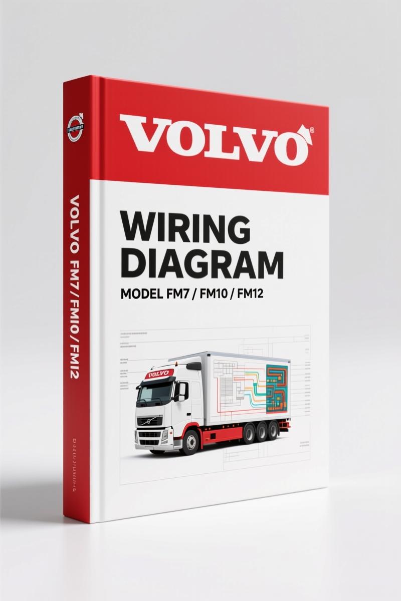
Volvo Penta FM12, FM7, FM10 Wiring Diagram (142 Pages)
Original price was: $35.75.$25.00Current price is: $25.00.
Factory wiring diagram for Volvo Penta FM12, FM7, FM10. 142 pages of electrical schematics, component locations, and connector pinouts.
Description
Volvo Penta FM12, FM7, FM10 Wiring Diagram – 142 Pages of Factory Circuits
I’ve seen more burnt wiring from guessing than from actual shorts. If you’re tracing a circuit on an FM12, you need the factory diagram. Not a reprint from some guy who scanned it with a potato. This is the real deal – a 142-page OEM wiring diagram from Volvo Penta for the FM7, FM10, and FM12 models. Every wire color, every fuse rating, every relay position is documented. Aftermarket sources will tell you “green wire goes to ground” and leave you hanging. This manual gives you the cable colour code table on page 138, the exact layout of the circuit card electrical centre on page 116, and the list of connectors starting on page 124. You want to diagnose a no-start on a Volvo Penta? Start here.
Component Wiring Diagrams – The Core of This Manual
The manual’s structure makes sense: it opens with an example wiring diagram (page 2) and a symbol glossary (page 3) so you don’t misread a ground symbol for a splice. Then the component wiring diagram index on page 5 points you straight to the system you need. Starting page 7, each subsystem – engine management, charging, starting, instrument panel – gets its own diagram. If you’ve ever used an aftermarket “universal” diagram that combines everything into one spaghetti mess, you’ll appreciate the clarity. Each diagram is labeled with component IDs that match the list on page 131.
Volvo Penta FM12, FM7, FM10 Wiring Diagram: What You Get
Here’s exactly what’s inside: illustrations index (page 53) followed by detailed illustrations of each harness and component location. Then the circuit card electrical centre (page 116) shows how the fuses and relays are arranged. Fuses are listed individually on page 117, relays on page 118. The cable harness illustration index (page 119) helps you identify which harness goes where. After that, the list of connectors (page 124) gives pin numbers and wire colors – critical when you’re repairing a damaged plug. All this is backed by the abbreviations (page 137) and cable colour code (page 138). No guesswork.
Why the Fuse and Relay Layout Matters on an FM12
The circuit card electrical centre section is worth the price alone. On a Volvo Penta FM12, the fuse box can be a nightmare if you don’t know which relay controls the ECU power or the fuel lift pump. Page 118 lists every relay and its function. Page 117 lists every fuse, including amp ratings. I’ve seen guys pull a 30-amp fuse, replace it with a 20 because that’s what they had, then wonder why the harness melted. The factory spec is there – use it. And if you need to understand how the electrical centre interacts with the rest of the truck, the component wiring diagrams tie it all together.
Cable Colour Code: Decoding the Factory Harness
Aftermarket wiring diagrams often use generic color abbreviations or guess the stripe patterns. The Volvo Penta manual gives you the full cable colour code table on page 138. For example, a wire marked “SB” means black (Swedish standard) – not blue, not silver. If you’re splicing into a harness on an FM10, you need that table. I’ve seen aftermarket diagrams list “GR” for green when the factory wire is actually “GN”. That mis-match will cost you hours. This manual also includes the list of connectors (page 124) with pin numbers matching the connector cavities – not the wire colors only. That level of detail is why I won’t touch an FM-series Volvo Penta without this document open on my bench.
External resources like Automotive Wiring can give you basic principles, but for exact wire colors and connector pinouts, you need the OEM source. Another reference like Automotive Wiring explains common practices, but it won’t tell you which wire on the FM12’s engine harness goes to the crank sensor. Only this manual does.
Does This Manual Include the List of Connectors?
Yes – page 124 through page 130 gives you a full list of connectors with part numbers, cavity counts, and wire assignments. If you’re replacing a damaged connector on an FM7, you’ll find the exact pin location and wire color. The list of components starting on page 131 then cross-references each electrical component (sensors, solenoids, etc.) to the diagrams. This is the kind of data that aftermarket “repair manuals” leave out because they’d have to pay licensing fees. This is the genuine Volvo Penta document.
For related wiring diagrams covering other Volvo models, check out VOLVO FM9 FM12 FH12 Wiring Diagram and VOLVO FM9 FM12 FH12 FH16 NH12 Service Manual Wiring Diagram. If you need a broader set, VOLVO FM9 FM12 FH12 FH16 NH12 Wiring Diagram covers additional chassis systems.
FAQ
- Is this manual for Volvo Penta marine engines or Volvo trucks?
- This wiring diagram was originally published for Volvo Trucks (FM7, FM10, FM12 RHD), but Volvo Penta used these same engine platforms. The wiring for the engine control, charging, and starting systems is identical. For marine-specific additions (like bilge pump circuits), you’d need the Volvo Penta marine supplement.
- What years are covered?
- The foreword states designs up to December 1998. This manual supersedes SM Group 37 TSP 104001. It covers FM7, FM10, and FM12 models produced through that date.
- Does this include wiring for the entire truck or just the engine?
- It covers the full vehicle electrical system – engine, instrument panel, lighting, chassis circuits, and the circuit card electrical centre. The component wiring diagrams (starting page 7) include subsystems like the ABS, transmission controls, and body modules. For a marine installation, the engine and instrument panel sections apply directly; the chassis and lighting sections may not be needed.
- Can I use this for left-hand drive versions?
- The manual is labeled RHD (right-hand drive). Wiring colors and component locations are identical for LHD, but the harness routing and some connector positions may differ. Use the cable colour code and component list to adapt. For exact LHD routing, find the corresponding LHD edition.
You’ve read this far because you know that a wiring diagram from a third party is a liability. The Volvo Penta FM12, FM7, and FM10 wiring diagram is the only document that gives you factory splice points, OEM fuse ratings, and the exact cable colours Volvo used. Don’t chase a ghost short with a multimeter and a prayer. Access the Factory Manual and start tracing circuits the right way.
Additional information
| Brand | Volvo Penta |
|---|---|
| Language | English |
2 reviews for Volvo Penta FM12, FM7, FM10 Wiring Diagram (142 Pages)
You may also like…
-
Sale!
Volvo Penta D12A, D6B, D12C Technical Manual – 23-Page Factory Abbreviation Reference
Original price was: $67.50.$50.00Current price is: $50.00. -
Sale!
Volvo Penta B7, B9, B12 2007 Wiring Diagram – Factory Electrical Schematics
Original price was: $71.10.$45.00Current price is: $45.00. -
Sale!
Volvo Penta FH, FM Technical Manual – Factory Specifications for Suspension & Emissions
Original price was: $79.00.$50.00Current price is: $50.00. -
Sale!

Volvo Penta TD520GE, TAD520GE, TD520VE, TD420VE, TAD420VE 2007 Workshop Manual
Original price was: $64.00.$50.00Current price is: $50.00.
Related products
-
Sale!

Technical Manual – International 6.0L Power Stroke FICM Diagnostics
Original price was: $29.80.$20.00Current price is: $20.00. -
Sale!

2005 Parts Catalog – International NGD 3.0 L Engine (77 pages)
Original price was: $44.70.$30.00Current price is: $30.00. -
Sale!

1991 Operators Manual – International Truck OEM Specs (108 Pages)
Original price was: $13.63.$10.99Current price is: $10.99. -
Sale!

1993 Operators Manual – International Bus 1000-3000 OEM Specs
Original price was: $12.30.$7.99Current price is: $7.99.
diy_master –
This is just what I needed. The document is high resolution. Contains detailed schematics for Volvo Penta. Saved my repair job! Thank you.
Richard G. –
Excellent quality! The file is very clear. A must-have for any Volvo Penta Penta mechanic doing repairs. Saved my weekend project! Thank you.