
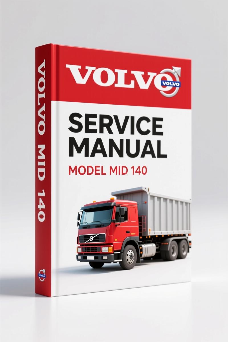
Volvo Michigan Euclid MID 140 Technical Manual – 21 Pages Factory Spec
Original price was: $40.00.$25.00Current price is: $25.00.
Factory electrical diagnostics for MID 140: breakout box pinouts, CAN 1/J1708 signal tables, 21 pages of OEM procedures.
Description
Volvo Michigan Euclid MID 140 Technical Manual – Pinout and Signal Diagnostics
You’ve got a MID 140 instrument cluster acting up, and the wiring diagram you pulled from some forum is wrong. I’ve seen it a hundred times. A misread voltage on a CAN line costs you an afternoon and a control unit. That’s why you need factory documentation. This Volvo Michigan Euclid MID 140 Technical Manual is 21 pages of direct pin-to-pin signal descriptions straight from the OEM. No reprints, no aftermarket guesswork. Just the voltages, resistances, and test points the factory engineers used.
Page one lays out the requirements: breakout box 9998551 with adapter 9998533, control unit connected, ignition in drive position, engine off. You measure DC voltage with a multimeter. That’s it. The manual gives you a table for Connector A (31 pins) and Connector B (25 pins) with nominal values. For example, terminal A1 (power supply) shows U ≈ Ubat relative to A2 ground. You get the signal type, measuring points, and notes like ‘SELECT active’ or ‘ESCAPE active’. Page 5 lists sensor inputs: fuel level (B3), battery charging (B8), outside temperature (B9), rear axle temperatures, gearbox oil temperature. All with U ≈ 0–5 V ranges.
MID 140 Breakout Box Setup – What You Need
You cannot skip the preparation. Connect breakout box 9998551 to adapter 9998533 between the control unit and the cable harness. The control unit must be powered. Turn the ignition key to the drive position, engine off. Use a multimeter set to DC voltage. This manual doesn’t assume you already know the pin assignments; it gives you the breakout box position and the corresponding control unit terminal in brackets. For example, measuring points 31–32 correspond to terminals A1–A2. Ground reference for sensors is on terminal A12 (42–32, U≈0 V).
Connector A Pinout: Power, Ground, and Control Lever Signals
Connector A covers the essential power and control signals. Terminal A1 (power supply kl 30) should read battery voltage. A2 is ground (0 V). A3 is power supply for the drive position (kl DR). A4 through A7 capture the control lever – SELECT, ESCAPE, ARROW UP, ARROW DOWN. Each shows 0 V when inactive and Ubat when active. A10 connects to SAE J1939 CAN 3 A (0–5 V). A15 and A16 carry CAN 1 A and B. A17 and A18 are SAE J1708 serial lines. The manual also notes a parking heater switch (A11) and audible acknowledgement signal (A21). If your MID 140 isn’t responding to lever inputs, you can pin-point exactly which wire is dead.
Connector B Pinout: Sensors and Grounding
Connector B is where the analog sensors live. Terminal B1 is ground (GND). B3 is fuel level sensor (0–5 V). B8 is battery charging voltage (1.3–9.1 V). B9 outside temperature, B10/B11 rear axle temperatures (front and rear), B12 gearbox oil temperature. All measured relative to B1 ground. The manual includes the same measurement points and nominal values. If you’re chasing a ghost code on the dash, start here. The values are tight – a 0.5 V deviation means a bad sensor or wiring. No generic manual gives you this.
21 Pages of Direct OEM Data – No Aftermarket Shortcuts
I’ve worked with aftermarket wiring diagrams that show three terminals on a connector that actually has eight. This Volvo Michigan Euclid MID 140 Technical Manual is an original factory document. Every pin is numbered, every signal type defined, every nominal value listed. The document includes reserved pins (A8, A20, etc.) so you know which lines are intentionally unused. It also covers the EOL (end-of-line) on A14. You won’t find that in a third-party scan. For anyone diagnosing a MID 140 instrument cluster, this is the only source you should trust. Pair it with the Volvo FH MID 144 Vehicle ECU Signal Descriptions Manual for similar pinouts on other Volvo models.
If you need to understand how the CAN bus interacts with the transmission, the Volvo FH I-Shift Transmission Description and Function Manual covers the I-Shift control logic. For engine-specific diagnostics, the Volvo D13A Engine Description Design and Function Manual gives you the mechanical side.
External references: check the Manual Transmission article on Wikipedia for transmission basics, and Manual Transmission for clutch and gearbox fundamentals.
Is This Manual Right for You?
If you’re a home garage enthusiast or a working mechanic dealing with a Volvo Michigan Euclid MID 140, and you’ve got a breakout box and a multimeter, this manual is your diagnostic bible. It does not cover engine overhaul, transmission rebuilds, or hydraulic circuits. It covers the instrument cluster signal descriptions – exact pinouts, voltages, and test conditions. That’s it. 21 pages, no filler. If you need torque specs for the head bolts, that’s a different book. But for electrical troubleshooting, this is the one.
- Does the manual include torque specifications for the MID 140?
- No. This manual is strictly electrical pinout diagnostics. Torque specs are in the separate service manual.
- Can I use this manual to diagnose a no-start condition on my Volvo Michigan Euclid MID 140?
- Yes, if the issue is related to the instrument cluster or CAN bus signals. The manual provides voltage and resistance values for each pin on connectors A and B. You will need a breakout box and multimeter. Follow the setup on page 1: ignition in drive position, engine off. Check power supply on A1 (U ≈ Ubat), ground on A2 (≈0V). Then proceed through each pin. For example, the SELECT control lever signal on A4 should show Ubat when active. If you get unexpected values, trace the wiring harness. This manual does not cover engine mechanicals or transmission internal diagnosis, but it is essential for electrical fault finding. Pair it with the other Volvo manuals linked above for a complete diagnostic workflow.
Stop chasing bad wiring with bad information. Access the Factory Manual and get the exact OEM data for your MID 140.
Additional information
| Brand | Volvo Michigan Euclid |
|---|---|
| Language | English |
4 reviews for Volvo Michigan Euclid MID 140 Technical Manual – 21 Pages Factory Spec
You may also like…
-
Sale!
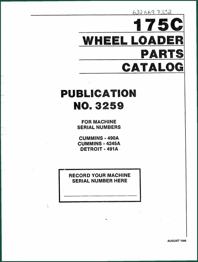
Volvo Michigan Euclid 175C 325 1988 Parts Catalog – 680-Page OEM Parts Breakdown
Original price was: $54.00.$40.00Current price is: $40.00. -
Sale!
Volvo Michigan Euclid 125C 1989 Parts Catalog – 418 Pages OEM Spec
Original price was: $55.10.$38.00Current price is: $38.00. -
Sale!
Volvo Michigan Euclid 125B Parts Catalog – OEM Parts Manual 473 Pages
Original price was: $58.00.$40.00Current price is: $40.00. -
Sale!

Volvo Michigan Euclid G900 Parts Catalog – 844-Page OEM Parts Reference
Original price was: $38.12.$31.50Current price is: $31.50.
Related products
-
Sale!

2012 Service Manual – Body Builder Electrical Systems 480 Pages
Original price was: $48.28.$34.00Current price is: $34.00. -
Sale!

1996 Operators Manual – International 1000-4000 Series (246 pages)
Original price was: $15.28.$9.99Current price is: $9.99. -
Sale!
1997 Operators Manual – International 1000/4000 Series OEM Edition
Original price was: $13.49.$9.99Current price is: $9.99. -
Sale!

Acura Integra 1998 Service Manual – 1891 Pages Factory OEM Documentation
Original price was: $31.75.$25.00Current price is: $25.00.
William H. –
I am so happy with this manual. Instant access after checkout process. Contains precise wiring diagrams for Volvo Michigan Euclid. Saves me hundreds of time.
diy_master –
This is exactly what I was looking for. Quick access after checkout. Contains precise wiring diagrams for Volvo Michigan Euclid. Saved my repair job! Thank you.
Richard G. –
I am extremely satisfied with this purchase. Instant access after checkout process. It guided me to troubleshoot my Volvo Michigan Euclid Michigan engine. Saved my weekend project! Thank you.
Robert M. –
This is exactly what I needed. The file is very clear. Every wiring layout is provided for Volvo Michigan Euclid Michigan. I will recommend this shop to others.