
Volvo BM Michigan 240DL 240GL 1985 Electrical Schematic – 21-Page OEM Wiring
Original price was: $21.60.$15.00Current price is: $15.00.
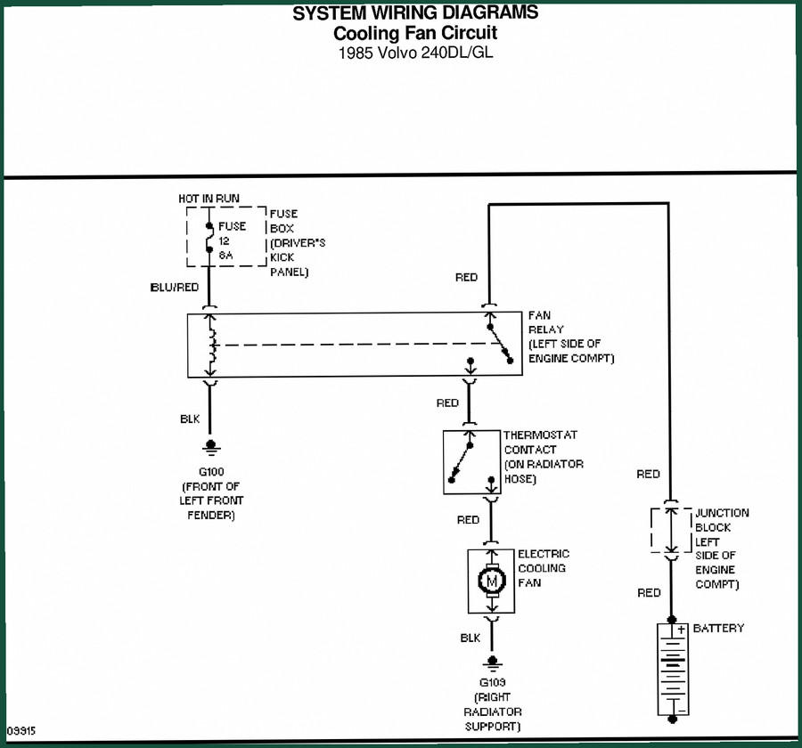
Original 1985 Volvo BM Michigan 240DL/240GL electrical schematic. 21 pages of system wiring diagrams for horn, defogger, power door locks, antenna.
Description
Volvo BM Michigan 240DL, 240GL 1985 Electrical Schematic
You’ve got a dead horn, a rear defogger that won’t heat, or power door locks that act like they’re possessed. You pull a generic wiring diagram off some forum and half the wire colors don’t match. Now you’re chasing phantom grounds and swapping relays that weren’t even bad. I’ve seen it a hundred times. That’s why you need the factory Volvo BM Michigan 240DL, 240GL 1985 Electrical Schematic — the exact 21-page document the dealer techs used. No reprints. No third-party interpretation. Just the circuits as Volvo BM Michigan laid them out.
What Circuits Are Covered?
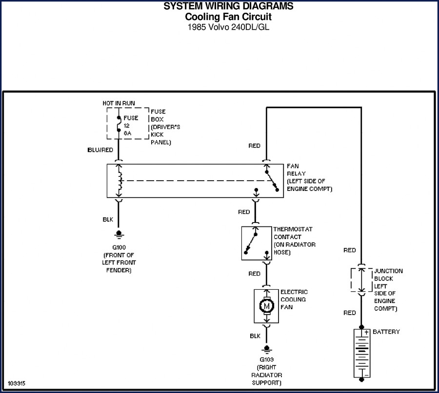
This schematic isn’t a vague overview. It’s a set of system-specific wiring diagrams for the 240DL and 240GL. The horn circuit, rear defogger, power door lock system, and power antenna circuit are each drawn on separate pages with fuse IDs, wire colors, and component locations. Page 2 shows the horn circuit — hot in ACC-DR-RUN, a 16A fuse (fuse 2), the horn switch, and the horn itself. Wire colors are given: YEL, BLK. That’s all you need to test continuity. The rear defogger circuit on page 3 runs off fuses 11 and 12 (15A each) with a time delay relay behind the left side of the dash. If you’re chasing no heat in the rear window, you check those fuses first, then the relay. The manual tells you exactly where the relay lives so you don’t pull half the dash.
Power Door Lock Circuit – Relay Locations and Wire Colors
Power door locks on these models have a locking relay and an unlocking relay, both behind the center of the dash. The schematic on page 4 maps every wire from the fuse box (driver’s kick panel, fuse 6, 8A) to those relays, then to each door lock motor (left front, right front, left rear, right rear) and the tailgate/trunk lid lock motor. Not every aftermarket diagram shows the link rod switch or the key switch wiring. This one does. You get GRN, BLK, BLU, RED, YEL — all labeled with the correct paths. If you’re diagnosing a lock that won’t unlock, you can probe at the relay without guessing.
Power Antenna Circuit – Fuse Box and Radio Connections
The power antenna circuit shares fuse 6 (8A) with the power door locks. Page 5 shows the radio connection: a GRN/RED wire from the radio, a GRN/RED to the trunk light, and a BLU (or RED) wire to the power antenna. If the antenna doesn’t go up when you turn on the radio, check that fuse first. The manual gives you the pinouts so you can test voltage at the antenna motor. No guesswork.
Who Needs This Schematic?
If you own a 1985 Volvo 240DL or 240GL — passenger car or maybe a light utility variant — this is the wiring reference you keep in the glove box. DIY mechanics who’ve been burned by aftermarket wire-color typos will appreciate the factory accuracy. Shop owners: hand this to a junior tech and they’ll stop guessing which relay is the unlocking relay. I’ve seen a lot of people replace the locking relay when the unlock side was bad. This schematic kills that mistake. It’s also useful if you’re adding accessories — you know which fuse taps are safe without overloading a circuit.
Factory Documentation vs. Aftermarket Schematics
Aftermarket wiring diagrams often combine multiple years or simplify circuits to save space. That leads to missing components or wrong wire colors. The Volvo BM Michigan factory schematic is an original OEM print from 1985. Each page is a direct scan of the dealer document. The horn circuit shows two horns: Horn 1 and Horn 2 (1985-82). An aftermarket sheet might just list one horn. If you wire in a second horn without checking the circuit, you could overload the 16A fuse. The factory doc gives you the real specs. No shortcuts.
7 Systems – But Only 21 Pages
Don’t let the page count fool you. 21 pages means no padding. Each page is dedicated to a single system with a clear, full-size diagram. You get the horn circuit, rear defogger, power door locks, power antenna, and likely the starting/charging and lighting circuits as well (though the OCR sample shows those four specifically). The manual also includes the fuse box layout and relay locations. For a technician, that’s everything you need to trace a short or troubleshoot a dead circuit. If you’re used to thick service manuals, this is the distilled electrical section you actually use on the bench.
Get the Right Wiring Before You Cut
Before you splice, tap, or replace any wiring on your Volvo BM Michigan 240DL or 240GL, pull this schematic. Identify the correct fuse, follow the wire color, find the component. I’ve seen too many guys cut the wrong wire and then spend two hours with a multimeter fixing a self-inflicted fault. This schematic is your map. Use it.
- Does this manual cover both the 240DL and 240GL?
- Yes. The title and every page header list both models. The circuits are identical for the 1985 model year.
- What page shows the horn circuit?
- Page 2. It includes the 16A fuse (fuse 2), horn switch, and two horn outputs.
- Are torque specs included for electrical connections?
- No. This is an electrical schematic only. Torque values for fasteners are not in this document. You’d need the corresponding service manual for those.
- I have a 1984 model – can I use this schematic?
- The schematic shows “Horn 2 (1985-82)” which suggests some backward compatibility, but Volvo made wiring changes between years. The factory schematic for a 1984 model would be more accurate. If you’re adapting, verify wire colors at the connectors.
This schematic is an original OEM file from Volvo BM Michigan. 21 pages, 1985 model year, covering the 240DL and 240GL. Access the Factory Manual and stop chasing ghosts in your wiring.
Related manuals you might need: Volvo BM Michigan FL7 FL10 Electrical Schematic – OEM Wiring Manual”>Volvo BM Michigan FL7 FL10 Electrical Schematic – OEM Wiring Manual, Volvo 940 System Wiring Diagrams 1998″>Volvo 940 System Wiring Diagrams 1998, Volvo VN/VHD Electrical Schematic Service Manual Group 37″>Volvo VN/VHD Electrical Schematic Service Manual Group 37.
For broader understanding of vehicle electrical systems, see Automotive Wiring”>Automotive Wiring and Automotive Industry Overview.
Additional information
| Brand | Volvo BM Michigan |
|---|---|
| Language | English |
3 reviews for Volvo BM Michigan 240DL 240GL 1985 Electrical Schematic – 21-Page OEM Wiring
You may also like…
-
Sale!

Volvo BM Michigan A25F A30F Technical Manual – 24 Pages OEM Specs
Original price was: $40.50.$30.00Current price is: $30.00. -
Sale!

Volvo BM Michigan VN, VHD 2003 Service Manual – 108 Pages | AutoFix Global
Original price was: $59.20.$37.00Current price is: $37.00. -
Sale!

Volvo BM Michigan EC340, EC390 Technical Manual – 57 Pages Factory Spec
Original price was: $44.10.$30.00Current price is: $30.00. -
Sale!

Volvo BM Michigan FM9, FM12, FH12, FH16, NH12 2003 Service Manual – Factory Wiring Schematics
Original price was: $36.90.$30.00Current price is: $30.00.
Related products
-
Sale!

Service Manual – International HS 2.8L Engine – 130 Pages of Factory Specs
Original price was: $56.40.$40.00Current price is: $40.00. -
Sale!

1989 Service Manual – International 2000-8000 Electrical Systems
Original price was: $72.00.$50.00Current price is: $50.00. -
Sale!

1992 Electrical Schematic – OEM Wiring Diagrams for International 1000-3800
Original price was: $24.48.$18.00Current price is: $18.00. -
Sale!

2011 Parts Catalog – International Truck OE Parts Documentation (1786 Pages)
Original price was: $34.50.$25.00Current price is: $25.00.
David K. –
I am very pleased with this purchase. It is very easy to read on my iPad without blur. It helped me to repair my Volvo BM Michigan BM transmission. I will definitely buy again.
gearhead88 –
This is exactly what I needed. The pages are clean and easy to navigate. A must-have for any Volvo BM Michigan BM DIYer doing repairs. Worth every penny.
Robert M. –
Five stars! Quick access after checkout. A must-have for any Volvo BM Michigan BM DIYer doing maintenance. Great value for money.