
Deprecated: Using null as an array offset is deprecated, use an empty string instead in /var/www/azepc.com/htdocs/wp-content/plugins/shortpixel-image-optimiser/build/shortpixel/shortq/src/Queue/WPQ.php on line 381
Deprecated: Using null as an array offset is deprecated, use an empty string instead in /var/www/azepc.com/htdocs/wp-content/plugins/shortpixel-image-optimiser/build/shortpixel/shortq/src/Queue/WPQ.php on line 381
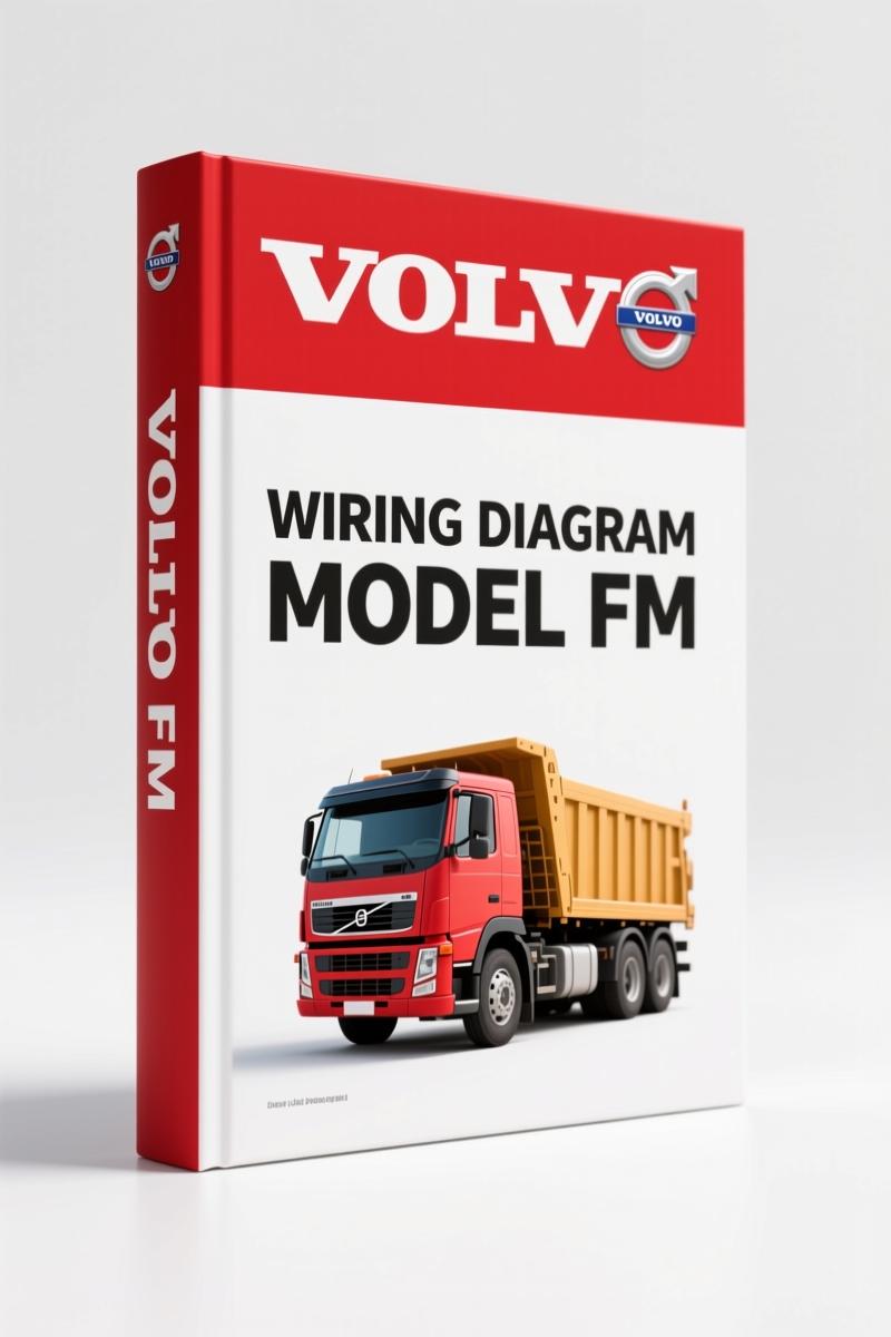
Volvo BM FM Wiring Diagram – 270-Page Factory Electrical Schematics
Original price was: $38.70.$30.00Current price is: $30.00.
270-page factory wiring diagram for Volvo BM FM. Includes all component schematics, fuse/relay layouts, ground points, and cable colour codes.
Description
Volvo BM FM Wiring Diagram
You’ve got a Volvo BM FM that won’t crank, and you’re staring at a mess of wires under the dash. The generic diagram you pulled from some forum shows pin 12 as the starter enable – wrong. You just fried a 400-dollar ECU. That kind of mistake costs time, money, and credibility. I’ve seen it happen more times than I can count. This 270-page Volvo BM FM Wiring Diagram is the factory document, not a third-party guess. It matches the production line prints from Volvo Truck Corporation, and it covers CHID ranges A698436-, B564590-, W100620-754005, and CKD891518-. If you’re working on an FM, this is the only wiring reference you should trust.
Volvo BM FM Wiring Diagram: Why OEM Matters
Aftermarket wiring diagrams are drawn from someone’s interpretation of a scanned page. They miss pin assignments, swap wire colors, and skip connector views. Volvo’s own document includes a cable colour code table on page 264 and a full list of connectors starting on page 237. Every wire – from the main power feed to the CAN bus pair – has a factory colour and a designation. You get the exact routing the harness builder used. That’s the difference between a fix that holds up and a call-back on a rainy Monday.
Component Wiring Diagrams and the 270-Page Scope
The manual opens with an example of a wiring diagram on page 2, then moves into the component wiring diagram index. Page 5 lists every subsystem – engine, transmission, brakes, HVAC, lighting, body electronics – with a reference to the page of the actual diagram. Component wiring diagrams run from page 9 through page 124. Illustrations (page 126 onward) show physical connector locations and harness routing. Fuses are listed on page 227, relays on page 229. Ground connections appear on page 234. You also get a list of components starting on page 252 – over twenty pages of part numbers and locations. This is not a skim-through pamphlet. It’s 270 pages of traceable, verifiable data.
Fuses, Relays, and Ground Connections – Factory Locations
Nothing wastes time like chasing a blown fuse that the diagram says is in position 23 but is actually under the passenger seat. Volvo’s illustration index (page 125) points you to the exact physical location drawing. The fuse table on page 227 shows amperage, circuit name, and which harness branch it protects. Relays on page 229 include coil resistance values and pin numbering per the factory standard. Ground connection points on page 234 are photographed and labeled with the chassis grounding stud number. You can confirm a bad ground by visual inspection because you know exactly which bolt to look for.
Read the Diagram Like a Pro: Cable Color Codes and Abbreviations
Volvo uses a two-letter code for cable colours: GN for green, BN for brown, OG for orange, etc. Page 264 lists every code used in the FM chassis. The abbreviations list on page 262 decodes every acronym – ESS, EMS, ABS, EBS, and the rest. When the diagram says “RD-2.5-BK” you know it’s a red wire, 2.5 mm² cross-section, with a black tracer. That level of detail saves you from probing the wrong wire. I’ve had junior techs spend an hour probing a harness because they guessed the colour. Don’t guess. Open the manual.
3 Reasons Aftermarket Wiring Schematics Fail
First, aftermarket drawings often omit the revision notes. Volvo issued service bulletins 370-160 and 370-161 to update the original wiring packages. The manual explicitly states which bulletins are superseded (order number 88956890). Second, aftermarket copies lose the connector shape and cavity numbers – critical when you’re backprobing a 48-pin module. Third, aftermarket schematics rarely include the component wiring diagram index. You end up flipping through 50 pages to find the window regulator circuit. With this manual, the index on page 5 gets you to the right diagram in under a minute. Automotive Wiring basics can help you understand circuits, but the specific pinout data belongs to Volvo.
Who This Manual Serves and a Real-World Example
You might be a heavy-equipment fleet mechanic or a home-garage owner who picked up a used FM for farm work. Either way, you need pinpoint accuracy when diagnosing electrical failures. Let’s say the truck has an intermittent no-start. The ECM isn’t waking up on key-on. Instead of throwing parts, you turn to the component wiring diagram for the engine control module (page 62, approximately – the index tells you the exact page). You check the main relay control circuit, find that the ECM receives power from relay 107 on the back of the fuse panel (page 229). You verify the ground at G701 (page 234). You confirm the CAN wiring to the instrument cluster with the list of connectors (page 237). The problem turns out to be a corroded pin at connector C30 – visible in the illustration on page 126. Half an hour of systematic diagnosis vs. three hours of guessing. Volvo FH FM Pneumatic Brake Circuit Diagram covers air systems, but this wiring diagram handles everything electrical.
Source Authenticity – OEM vs. Aftermarket
This is a direct PDF scan of Volvo Truck Corporation’s official service documentation, part number 88956890. The foreword (page 2) carries a copyright statement and a warning to check the latest wiring diagrams site for updates. Aftermarket reprints from third-party sellers often strip the revision histories and safety warnings. You see the original Volbo standard time (V.S.T.) operation numbers in the margins. That means a professional shop in Sweden or the U.S. used exactly this document to bill warranty repairs. If you need a complementary reference, VOLVO FM FH Wiring Diagram covers the FH series as well. For the earlier FE model, see Volvo BM FE 2007 Wiring Diagram – Factory OEM Manual (190 Pages). Automotive Wiring resources can supplement your general knowledge, but for your FM, trust the factory print.
- Does this manual cover the Volvo BM FE model?
- No. This wiring diagram is specific to the FM chassis with the CHID ranges listed on page 1. The FE uses a different harness architecture.
- How are the 270 pages organized?
- The manual begins with an example of a wiring diagram (page 2), then a component wiring diagram index (page 5). Component wiring diagrams span pages 9–124. A separate illustrations section (page 126) shows connector shapes and locations. Fuses are on page 227, relays on page 229. Wiring harness illustrations start on page 231, ground connections on page 234, list of connectors on page 237, list of components on page 252, abbreviations on page 262, and cable colour code on page 264. Each section is numbered and bookmarked for quick navigation.
- Can I print the diagrams?
- Yes. The PDF is high resolution. Print at 100% scale to maintain connector cavity dimensions. Do not scale to fit – that distorts wire routing.
- Is a printed version available?
- This is a digital access only. You receive the full 270-page PDF file. Print as many copies as you need for your shop or field truck.
Every electrical repair on a Volvo BM FM carries risk if you use the wrong data. The factory wiring diagram gives you the actual wire colours, pin locations, fuse ratings, and ground points that the engineers designed. Stop chasing ghosts. Stop replacing parts that tested good. Access the factory manual.
Additional information
| Brand | Volvo BM |
|---|---|
| Language | English |
3 reviews for Volvo BM FM Wiring Diagram – 270-Page Factory Electrical Schematics
You may also like…
-
Sale!

Volvo BM VN, VHD Service Manual – 104 Pages Factory Preventive Maintenance
Original price was: $60.80.$40.00Current price is: $40.00. -
Sale!

Volvo BM 4600 1984 Parts Catalog – OEM Factory Parts Identification
Original price was: $70.20.$45.00Current price is: $45.00. -
Sale!

Volvo BM P1800 Service Manual – 220 Pages Factory OEM Specs
Original price was: $49.60.$40.00Current price is: $40.00. -
Sale!

Volvo BM L120D Service Manual – 603 Pages Factory OEM Documentation
Original price was: $64.35.$45.00Current price is: $45.00.
Related products
-
Sale!

1993 Electrical Schematic – International 1000/3000/4000 Bus Chassis OEM Wiring Diagrams
Original price was: $29.26.$22.00Current price is: $22.00. -
Sale!

2011 Parts Catalog – International 7400 SFA 6X6 – 1886 Pages of OEM Part Numbers
Original price was: $32.00.$25.00Current price is: $25.00. -
Sale!

Service Manual – International HS 2.8L Engine – 130 Pages of Factory Specs
Original price was: $56.40.$40.00Current price is: $40.00. -
Sale!

2005 Parts Catalog – International NGD 3.0 L Engine (77 pages)
Original price was: $44.70.$30.00Current price is: $30.00.
Robert M. –
Excellent OEM spec sheet. It is easily zoomable on my iPad without blur. It helped me to fix my Volvo BM BM electrical system. Saved my repair job! Thank you.
David K. –
Superb resource! The file quality is excellent. Contains precise schematics for Volvo BM. Saves me a lot of money.
Thomas B. –
I am so happy with this purchase. Immediate link after checkout process. Every spec sheet is provided for Volvo BM BM. Saved my repair job! Thank you.