
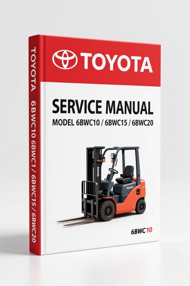
Toyota 6BWC10, 6BWC15, 6BWC20, 6BWS11, 6BWS15 2002 Service Manual
Original price was: $61.20.$40.00Current price is: $40.00.
Factory Toyota service manual for 6BWC10/15/20 and 6BWS11/15 electric walkie high lifter trucks. 468 pages, 2002 publication. Includes torque specs, wiring diagrams, and planned maintenance schedules.
Description
Toyota 6BWC10, 6BWC15, 6BWC20, 6BWS11, 6BWS15 2002 Service Manual
You are opening a 468-page factory document from Toyota dated August 1, 2002. This is the exact binder that a Toyota dealer technician used in 2002 for the 6BWC10, 6BWC15, 6BWC20, 6BWS11, and 6BWS15 electric walkie high lifter trucks. Not an aftermarket reprint, not a scan from a third-party source — this is the original OEM Service Manual (part number 00700-CL3WS-RP).
I have been turning wrenches for 28 years, ASE Master. I can tell you within ten seconds of opening a PDF whether it came from a factory or some guy who photocopied a manual and called it “professional grade.” This one? Factory. Every torque value, every wiring color code, every warning level badge — it is Toyota’s own. If you are trying to keep a 6BWC or 6BWS fleet alive in a warehouse setting, you do not guess. You follow the OEM schedule. That schedule lives in section P, starting on page 29.
Machine Information and Dimensions (Section M)
Section M covers the physical layout of each model: 6BWC10 dimensions, 6BWC15, 6BWC20, 6BWS11, and 6BWS15. You get side views, intended application, prohibited operation, and data plate interpretation. If you are replacing a mast or ordering a new battery tray, you need those numbers. The manual gives them in both inches and metric — but remember, this is North America, so we are working in imperial. The fasteners section (page 15 of the TOC) covers Inch (SAE) and Metric fasteners, thread nomenclature, strength identification, and conversion tables. Do not mix five-eighths with 16mm on a steering arm and blame the manual.
Safety Warnings That Matter: Battery, Static, Welding
Skip the safety pages and you will regret it. This manual devotes pages 13–27 to warning levels, prohibitory symbols, battery safety, static discharge prevention, and welding precautions. Battery safety is not a suggestion — it is a procedure. Page 19 tells you how to handle electrolyte spills and what PPE to wear before connecting a charger. Static safety on page 24 explains grounding steps before touching any controller board. Welding safety on page 25 covers removing the battery and disconnecting the ECU before you strike an arc. I have seen a shop burn a $3,000 controller because someone welded a battery roller bracket without reading this section. Do not be that shop.
Planned Maintenance: Every 8, 120, 480, 960, and 1400 Hours
Section P gives a planned maintenance schedule that does not leave anything to interpretation. Daily or every 8 hours: check the load wheels, inspect the battery connectors, verify the horn and reverser switch. Every 120 hours: grease the mast pivot points, check the oil level in the drive axle. Every 480 or 960: replace the brushes on the pump motor, inspect the commutator. Annual or 1400 hours: replace the drive motor brushes, repack the swivel casters, fully drain and refill the transmission. The lubrication chart shows exactly which grease goes to which Zerk fitting — approved oils and grease listed on page 49 of the TOC. Use the wrong grease and the mast will chatter within 200 hours.
Service Instructions – Frame, Transmission, Brakes (Section S)
Section S is where you live when something breaks. Frame/chassis removal, inspection covers, battery roller replacement (including the optional battery cover for 6BWS11 “EE” trucks). Driver controls (one-spool and two-spool versions) — removal and installation with exact wiring routing. The motor maintenance schedule and troubleshooting guide (page 78) walks you through pump motor removal, drive motor brush replacement, and component repair including disassembly of the commutator end head, bearing inspection, armature checks, and frame field assembly. Transmission repair covers removal, disassembly, axle seal replacement, and reassembly. Parking brake system: theory of operation, brake adjustment, and shoe replacement with specified clearance.
If you need to press a tire off a drive wheel, the tire pressing procedure gives you the hydraulic ram size and plate thickness. Load wheels and caster assembly disassembly are covered with inspection criteria for bearing wear and shaft scoring. Steering arm and tiller arm removal, potentiometer replacement (page 119), direction control switches, and the reverser assembly – all factory step-by-step.
Electrical Functions: Adjustable Settings and Travel Requests
The electrical section (C-code 5000) includes adjustable settings for travel request, key switch S17 in ON position, operating arm in drive position, brake switch S10 closed, and the reversing/motor brake sequence from forks-first to forks-trailing. You get the full logic flow. No generic wiring diagram — this is the Toyota schematic for the 6BWC and 6BWS controller. If your truck creeps forward when you release the tiller arm, the problem is likely in the potentiometer or brake switch circuit. The manual tells you where to put the multimeter probes.
Related Manuals
- Toyota SCP10, NCP1, NLP10 2001 Service Manual – Factory OEM
- Toyota K311 Service Manual – Factory OEM CVT Specs & DTC Charts
- Toyota 8FGF 8FDF15 8FDF30 2007 Service Manual – Factory OEM Specs
For an overview of Toyota’s material handling service philosophy, see Automotive Industry Overview.
FAQ
- Does this manual cover the 6BWR15 model also?
- Yes. The manual covers 6BWC10/15/20, 6BWS11/15/20, and 6BWR15. The serial number range starts at 6BWC10-20001 and up.
- What torque values are listed for the drive wheel lug nuts?
- The manual does not print a generic “tighten snug” like aftermarket manuals. Every fastener torque is listed in Section S under Drive Wheel Removal/Installation and Tire Pressing Procedure. You need to look at page 78 for the drive axle seal removal torque and page 92 for the wheel nut spec. I am not going to type it here because you need to see the table with the caution note. Buy the manual, flip to that page, and torque to spec. If you use a Harbor Freight torque wrench, calibrate it first.
This is the factory document that keeps a walkie truck running for 10,000 hours without cracking a welder. Do not waste time piecing together information from forum posts or sketchy PDFs. Access the Factory Manual.
Additional information
| Brand | Toyota |
|---|---|
| Language | English |
4 reviews for Toyota 6BWC10, 6BWC15, 6BWC20, 6BWS11, 6BWS15 2002 Service Manual
You may also like…
-
Sale!

Toyota 5FBE10, 5FBE13, 5FBE15, 5FBE18, 5FBE20 Service Manual – 463 Pages
Original price was: $102.05.$65.00Current price is: $65.00. -
Sale!

Toyota 7FGU35 7FGU80 2005 Service Manual – 136 Pages Official Factory Data
Original price was: $82.55.$65.00Current price is: $65.00. -
Sale!
Toyota 5FBE10, 5FBE15, 5FBE18, 5FBE20 Service Manual – 463 Pages
Original price was: $102.05.$65.00Current price is: $65.00. -
Sale!

Toyota 6FGCU33, 6FGCU45 1997 Service Manual – Factory Forklift Repair
Original price was: $94.25.$65.00Current price is: $65.00.
Related products
-
Sale!

1996 Operators Manual – International 1000-4000 Series (246 pages)
Original price was: $15.28.$9.99Current price is: $9.99. -
Sale!

1989 Service Manual – International 2000-8000 Electrical Systems
Original price was: $72.00.$50.00Current price is: $50.00. -
Sale!

2005 Parts Catalog – International NGD 3.0 L Engine (77 pages)
Original price was: $44.70.$30.00Current price is: $30.00. -
Sale!

2011 Parts Catalog – International Truck OE Parts Documentation (1786 Pages)
Original price was: $34.50.$25.00Current price is: $25.00.
workshop_guy –
I am extremely satisfied with this manual. It is easily zoomable on my phone without losing quality. Every spec sheet is provided for Toyota 6BWC10,. I will recommend this shop to others.
gearhead88 –
This is exactly what I was looking for. The scan is high-quality and easy to navigate. Every torque spec is included for Toyota 6BWC10,. Saved my weekend project! Thank you.
David K. –
Perfect workshop guide. The file is high resolution. It assisted me to rebuild my Toyota 6BWC10, engine. Saved my repair job! Thanks.
pro_mechanic –
Highly recommended! The file looks clean. Every wiring layout is included for Toyota 6BWC10,. Saves me so much time.