
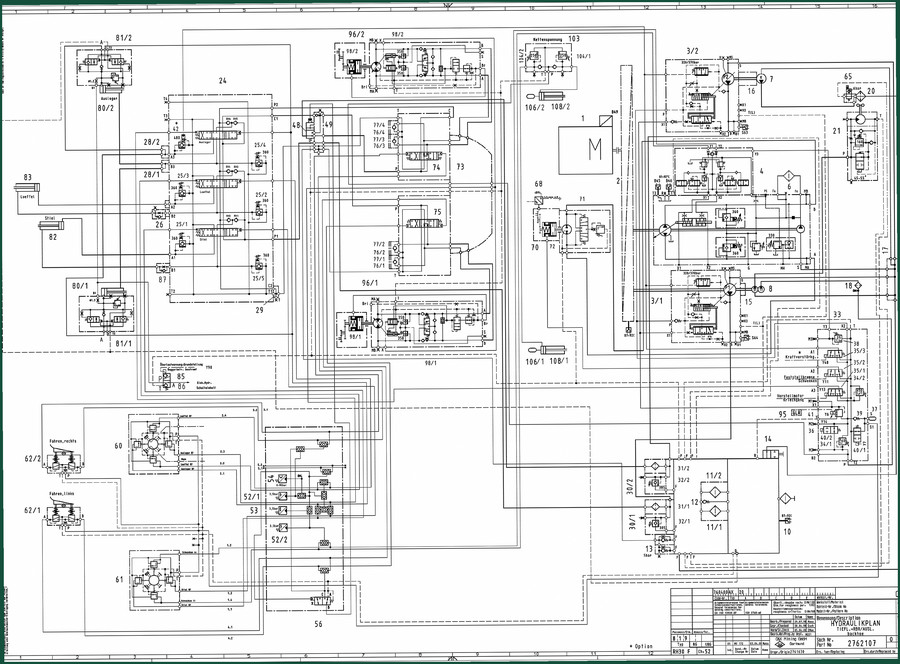
Terex RH 30 F Hydraulic Schematic – Factory OEM Diagram 13 Pages
Original price was: $13.29.$9.99Current price is: $9.99.
OEM 13-page hydraulic schematic for Terex RH 30 F. Includes circuit diagram, component list, and pressure settings for certified technicians.
Description
Terex RH 30 F Hydraulic Schematic – OEM Factory Diagram for Hydraulic System
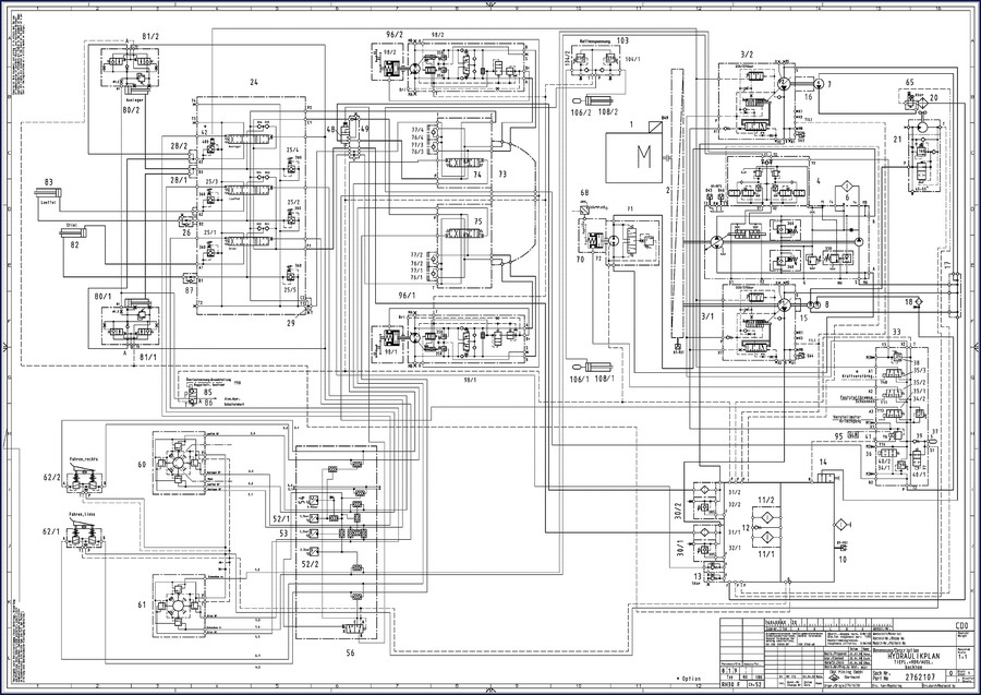
You’ve got a Terex RH 30 F with a hydraulic problem — maybe the boom won’t hold, the track drive is sluggish, or you’re chasing a pressure drop. Without the factory schematic you’re tracing lines blind, hoping the aftermarket copy is correct. This OEM hydraulic schematic from Terex gives you the exact system layout. 13 pages. Factory pressure ratings, valve IDs, flow paths, and component callouts. I’ve seen too many guys blow a seal because they guessed the relief setting. This diagram kills that guesswork.
Terex RH 30 F Hydraulic Schematic: 13 Pages of OEM Data
The manual is a direct scan of the original Terex (O&K Mining) hydraulic circuit drawing. It covers the RH 30 F backhoe configuration. Page 1 is the full schematic — every line, every valve, every pressure tap. Page 8.3-1 lists the technical data for the system: main pump flow, swing pump specs, and the item numbers for components like the 3-spool valve block (item 24) and pressure relief valves (items 25). That’s the kind of detail you get when you work from factory originals.
Why OEM Documentation Matters for Hydraulic Repairs
Aftermarket manuals often redraw schematics and introduce errors — wrong port labels, missing anti-cavitation valves, or incorrect pressure ranges. This is an OEM print, part number 2 762 107 (00). It reflects what the engineers designed. If you’re rebuilding a main pump or adjusting the overload warning system (Y90), you need the factory circuit. No substitutions.
Reading the Diagram: Valve Locations and Pressure Ratings
The schematic uses a clear component grid. Look at the boom circuit: items 77/4, 76/4 feed the boom cylinder through pressure relief valves RV4 and RV3. The diagram shows the setting range (320/370 bar) right on the lines. For the track motors, follow items 96/2, 98/2 and the chain tension circuit (item 103). Each valve block has a location label — superstructure, boom, or undercarriage. The item numbers match the factory parts catalog, so cross-referencing is straightforward.
Pilot Pressure and Overload Warnings
Safety is built into the diagram. The overload warning system (Grundstellung Y90) is shown with its electrical/hydraulic switching (Elek. Hydr. Schalteinbelt). The pilot pressure circuit starts at item 31/2, regulated to 5 bar. If you’re troubleshooting a drift or a non-responsive control, check the pilot supply first. The schematic also includes the tank pre-charging valve (item 13) and return filter bypass (item 12). Don’t skip those — a clogged filter can mimic a pump failure.
Use the Pump Pressure Specs to Diagnose Drift
Page 8.3-1 gives the system technical data. The main pumps (item 3) are rated at 320/370 bar. The swing pump (item 4) has its own circuit. When you’re seeing drift in the boom, check the anti-cavitation valves on the 3-spool block (items 25). Compare actual pressures against the factory numbers. This schematic tells you exactly where to put your gauge — no guessing.
For related equipment that shares similar hydraulic architecture, look at the TEREX LIFTING TX77-45R Spare Parts Catalogue 2002 for component IDs, or the Terex PPM AC35 Technical Manual for crane hydraulic data. The Terex Pegson Premiertrak 1100×650 & 26×44 User Manual covers crusher hydraulics if you work in quarry operations.
Understanding Hydraulic systems fundamentals helps when reading any schematic. For industry context on heavy equipment reliability, see the Automotive Industry Overview.
- Does this schematic include torque specs for hydraulic fittings?
- No, this is a hydraulic circuit diagram only.
- How do I use this schematic to diagnose a boom drift issue on the RH 30 F?
- Start by locating the boom circuit on the schematic (items 77/4, 76/4, and valves RV4/RV3). Check the pilot pressure at item 31/2 — it must be 5 bar. Then measure pressure at the main pump lines (item 3) against the 320/370 bar rating. If drift persists, inspect the anti-cavitation valves (items 25) on the 3-spool block. The diagram shows the exact flow path; use the item list on page 2 to find component locations in the machine. Without this factory schematic you’d be pulling housings unnecessarily. It saves you hours of dead-end tracing.
That’s the difference between working with a factory schematic and a guess. If you’re serious about getting the RH 30 F hydraulic system right, don’t rely on copied diagrams. Access the Factory Manual from AutoRepairManuals — the largest collection of OEM shop manuals in North America with verified factory specifications.
Additional information
| Brand | Terex |
|---|---|
| Language | English |
3 reviews for Terex RH 30 F Hydraulic Schematic – Factory OEM Diagram 13 Pages
You may also like…
-
Sale!
Terex AC200-1 Training Manual – Boom Dismantling & Assembly OEM Procedures
Original price was: $93.75.$75.00Current price is: $75.00. -
Sale!

Terex TA40 G7 2006 Parts Catalog – OEM Parts Documentation
Original price was: $32,400.00.$24,000.00Current price is: $24,000.00. -
Sale!
Terex AC200-1 Training Manual – Brake System Factory Specs
Original price was: $91.50.$75.00Current price is: $75.00. -
Sale!
Terex PT-70 2010 Parts Catalog – 34 Pages OEM Part Numbers
Original price was: $30,480.00.$24,000.00Current price is: $24,000.00.
Related products
-
Sale!

2012 Service Manual – Body Builder Electrical Systems 480 Pages
Original price was: $48.28.$34.00Current price is: $34.00. -
Sale!

Acura NSX 1991 Service Manual – 1420 Pages OEM
Original price was: $102.05.$65.00Current price is: $65.00. -
Sale!

Service Manual – International HS 2.8L Engine – 130 Pages of Factory Specs
Original price was: $56.40.$40.00Current price is: $40.00. -
Sale!

Technical Manual – International DT 530 & HT 530 (118 Pages)
Original price was: $37.00.$25.00Current price is: $25.00.
diy_master –
I am very pleased with this manual. It is easily zoomable on my laptop without losing quality. Every wiring layout is provided for Terex RH. Saved my weekend project! Thanks.
pro_mechanic –
I am very pleased with this manual. It is easily zoomable on my iPad without blur. Every torque spec is provided for Terex RH. Highly recommended for mechanics.
gearhead88 –
Superb resource! Instant access after checkout process. It guided me to repair my Terex RH engine. Worth every penny.