
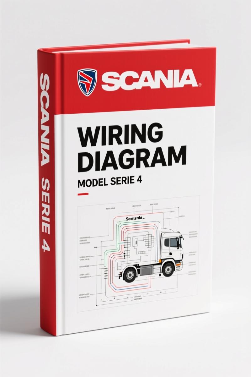
Scania Serie 4 1997 Wiring Diagram – 910 Pages Factory Electrical Data
Original price was: $56.25.$45.00Current price is: $45.00.
Factory Scania wiring diagram for Serie 4 (1997). 910 pages covering all electrical components, connectors, and control units.
Description
Scania Serie 4 1997 Wiring Diagram – OEM Factory Specs, No Guesswork
You’ve got a Scania Serie 4 in the bay with an electrical gremlin – maybe a brake light that stays on, a starter that won’t crank, or a trailer module that’s dead. Before you start backprobing connectors with a test light and hoping, you need the actual factory wiring documentation. Not a redrawn aftermarket schematic that swapped two pins and left out the resistor pack. The Scania Serie 4 1997 Wiring Diagram is the real OEM document – 910 pages of component codes, circuit diagrams, and connector pinouts that came off Scania’s own engineering system. I’ve been turning wrenches for 28 years, and I won’t touch a truck’s electrical system without the factory book. This one saves you the tow truck call.
Componentes Eléctricos: What’s Inside Section 16:06-11
The main electrical section, 16:06-11 Componentes eléctricos, is broken into logical subsections that mirror how a real truck is wired. You get A – General Instructions covering wire splicing, fuse sizing, and cable cross-section calculation in imperial (AWG equivalents are listed). B – Brake switches and interrupters, including the B1 brake light switch, B11-B13 differential lock switches, B25 accelerator idle and full-throttle sensors, B27 clutch depressed switch, B34 brake pedal switch, and B49 manual exhaust brake. Each component has its own page with pin numbers, wire colors, and the exact circuit path.
C – Connectors: every style used on the Serie 4 – AMP Mate’n Lock, Cannon Sure Seal, Coni, Deutsch DT, DIN, Pipa, and Scania’s own connectors. There’s a connector location drawing and cavity numbering. If you’ve ever tried to backprobe a Deutsch DT without knowing which cavity is which, you know why this section matters. D – Diodes and resistors: D1 fan resistor, D18 diode unit for the trailer, D35 accelerator pedal diodes, D500 diode pack. E – Control units: E7 VPS control, E9 Webasto DW 80, E10 ADR current limiter, E11 SRS airbag module, E12 EDC engine control, E17 ETC transmission control, E21 lift axle control, E26 starting pre-heater, E27 12V converter for trailer, E42 12V converter for headlights, E45 ACL pump, E46 trailer detection unit, E500 signal amplifier. H – Electrothermal equipment: H10 glow plug for starting pre-heater, H14 airbag igniter, H15 fuel heater, H18 water separator filter heater. K – Communication connections: K1 diagnostic socket. L – Lights: full light code tables, L1-L4 driving lights, L7-L10 position and turn signals, L52-55 roof combination lights, L56-58 bunk lights. M – Electric motors: M2 wiper motor, M3 fan motor, M5-M6 headlight wipers, M7-M8 headlight washers, M9-M10 window regulators, M12 sunroof, M14 rear wiper motor. That’s the kind of detail that keeps a $300 diagnostic call from turning into a $3,000 rewire.
3 Key Sections That Save You from Dead Ends
First – the Lista de componentes (component list) starting around page 4. Every electrical component has a code, a short description, a reference to a position figure, and the electrical diagram number. Second – the Diagramas de circuito (circuit diagrams) from page 68. These are full-page schematics with numbered sections. The table on page 68 tells you which section contains which function. Third – Figuras de posición starting page 78. These show exactly where each component lives on the chassis – cab interior, engine bay, frame rails. Left-hand and right-hand drive positions are noted. No flipping back and forth between three different manuals.
Does the Wiring Diagram Cover the Fuel System?
Yes – indirectly. The fuel heater (H15) and the water separator heater (H18) are in the electrothermal section. The EDC control unit (E12) manages fuel injection. But the manual is a pure wiring diagram, not a repair manual. You won’t find fuel line routing or injector service specs here. What you get is the exact wire from the engine harness to the EDC connector, including pin numbers and wire gauge. For a fuel system electrical diagnosis – say, a no-start with no injection pulse – this diagram is your roadmap.
Source Authenticity: Why Aftermarket Schematics Fail
I’ve seen aftermarket wiring books that merged two different truck configurations into one drawing and left out the ground wire for the ADR system. That’s a fire risk. This manual is a direct scan of the original 1997 Scania publication, part number 1 585 931, printed by Scania CV AB. The Spanish language edition (Edición 2 es) is the same content as the original Swedish book – all schematics and component codes are language-independent. The file name begins with 160101ES.pdf – that’s Scania’s own part family identifier. You’re getting the same document a Scania dealer technician would pull up on their terminal.
Who Needs This Manual
If you’re a home mechanic working on a Serie 4 truck you bought at auction, this manual keeps you from frying the ECU when you miswire a sensor. If you’re a shop owner in the North American market (remember, these are European trucks but they’re common in fleets here), you’ll use it to validate every wire you replace. The OBD connector pinout is in section K1 – page 68 of the PDF. Beginners: don’t touch the Webasto pre-heater wiring without looking at the E9 control unit diagram first. The 12V converters for trailer and headlights are separate circuits – page 73 gives you the charge pressure? No, that’s a different manual – but the converter location is in the position figures. Scania 4 Series 1997 Wiring Diagram – OEM Factory Handbook is the base document; if you need more context on the engine control side, see the Scania D1LC 1996 Installation Manual – Factory Retrofit Guide for the Webasto system, and the Scania R, T 1999 Installation Manual – Webasto Heater Guide for later models.
- Is the manual in English?
- No – it’s in Spanish. But wiring diagrams, component codes, and connector pinouts are universal. You don’t need to speak Spanish to read a circuit drawing.
- How are components identified in the manual?
- Each component gets a unique code (e.g., B1 for brake light switch, E12 for EDC control). The Lista de componentes on page 4 lists every code with its function, position figure reference, and diagram number. The cable marking system (section 7) explains how wire numbers relate to circuit functions. For example, a wire marked 1.2 means circuit 1, section 2. This system is detailed on page 71. You can trace any wire from the component to the fuse panel using the code system.
So you’ve got a Serie 4 with a dead taillight circuit. You pop the manual open to section L – Luces. You find the light code table, then the circuit diagram for L7-L10. You see the wire number, follow it to the connector diagram in section C, and realize the ground splice is in a Deutsch DT connector behind the left rear wheel. That’s a 15-minute fix instead of a three-hour chase. That’s why you Access the Factory Manual – it’s the difference between guessing and knowing.
- Related: Scania 4 Series 1997 Wiring Diagram – OEM Factory Handbook
- Related: Scania D1LC 1996 Installation Manual – Factory Retrofit Guide
- Related: Scania R, T 1999 Installation Manual – Webasto Heater Guide
External references: Automotive Wiring, Automotive Wiring
Additional information
| Brand | Scania |
|---|---|
| Language | English |
2 reviews for Scania Serie 4 1997 Wiring Diagram – 910 Pages Factory Electrical Data
You may also like…
-
Sale!
Scania Comfort Shift, CS 1997 Service Manual – 67 Pages
Original price was: $69.50.$50.00Current price is: $50.00. -
Sale!
Scania CP12 1995 Diagnostics Manual – Bosch ABS/TC System
Original price was: $73.50.$50.00Current price is: $50.00. -
Sale!

Scania T cab 11-16 Litre 2002 Repair Manual – Fuel System Specs
Original price was: $72.60.$60.00Current price is: $60.00. -
Sale!
Scania 4-series 1999 Service Manual – Factory ABS/TC Diagnostics
Original price was: $70.00.$50.00Current price is: $50.00.
Related products
-
Sale!

1991 Electrical Schematic – 112-Page OEM Wiring Diagram for International 1000-3000 Series
Original price was: $22.75.$17.50Current price is: $17.50. -
Sale!
1995 Operators Manual – International 1000-4000 Series | OEM Documentation
Original price was: $12.49.$9.99Current price is: $9.99. -
Sale!

Acura Integra 1998 Service Manual – 1891 Pages Factory OEM Documentation
Original price was: $31.75.$25.00Current price is: $25.00. -
Sale!
International 1000-3000 Series Operators Manual – 132 Pages of OEM Specs
Original price was: $14.40.$10.99Current price is: $10.99.
pro_mechanic –
This is exactly what I was looking for. The document is high resolution. Contains detailed wiring diagrams for Scania. Saves me so much time.
David K. –
Perfect OEM spec sheet. The PDF is high resolution. A must-have for any Scania Serie mechanic doing maintenance. Great value for money.