
Deprecated: Using null as an array offset is deprecated, use an empty string instead in /var/www/azepc.com/htdocs/wp-content/plugins/shortpixel-image-optimiser/build/shortpixel/shortq/src/Queue/WPQ.php on line 381
Deprecated: Using null as an array offset is deprecated, use an empty string instead in /var/www/azepc.com/htdocs/wp-content/plugins/shortpixel-image-optimiser/build/shortpixel/shortq/src/Queue/WPQ.php on line 381
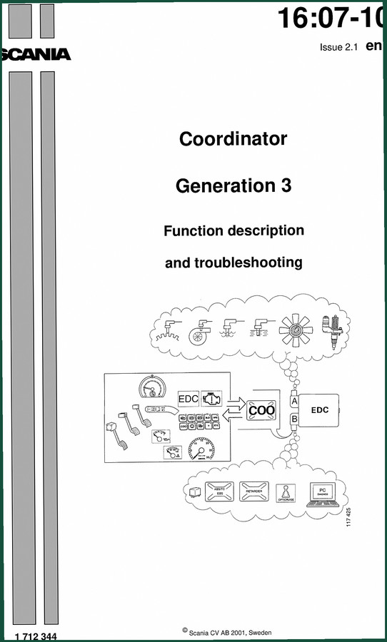
Scania Coordinator 2001 Technical Manual – Factory Diagnostics & Wiring
Original price was: $37.50.$25.00Current price is: $25.00.
Factory Scania Coordinator 2001 technical manual covering CAN communication, fault codes, wiring diagrams, and component diagnostics.
Description
Scania Coordinator 2001 Technical Manual
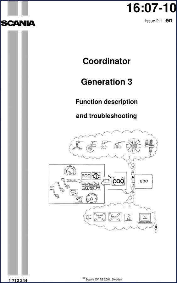
I’ve seen more than a few techs waste an afternoon chasing a signal that wasn’t there because they didn’t have the right wiring diagram. This Scania Coordinator 2001 Technical Manual fixes that. It’s 31 pages of factory documentation, not some aftermarket rewrite. If you’re working on a Coordinator Generation 3, you need the actual OEM procedure.
Coordinator Generation 3: Function Description Overview
Starts on page 3 with the general function. The coordinator sits in the cab and acts as a data relay between driver controls and the engine control unit. It covers CAN communication, interaction with Retarder, ABS/TC, EBS, and Opticruise. The manual includes a section titled “Why use Scania Diagnos?” explaining how that diagnostic tool interfaces with the coordinator. No guesswork about which control unit talks to which. Page 19 shows how to read and clear fault codes using the diagnostic switch panel S50. You don’t need a scan tool – the manual shows how to flash codes using the warning lamps.
Get the manual.
What Does the Manual Cover for Brake Pedal Switches?
Two switches are documented: B1 and B34. The manual explains their role in the brake circuit and how the coordinator interprets their signals. B1 is normally open, B34 normally closed. The coordinator compares them to detect a stuck pedal or wiring fault. If you get fault code 21, this section tells you exactly what to measure. If you’re chasing a brake light fault or a transmission lockout, this section saves you from pulling your hair out. The wiring is on page 30.
Components: Accelerator Pedal Sensor to Tachograph
Each component gets its own subsection – accelerator pedal sensor B25/B26/D35, cruise control switch S51, clutch pedal switch B32, tachograph O4, indicator warning lamps W27/W4, diagnostic switch panel S50, coolant temperature gauge O7, oil pressure gauge O8, and bodywork equipment connector C271. The manual tells you where each is located and what signals they send. For example, the tachograph section includes wiring to the speed sensor. This level of detail is what you pay for when you buy OEM.
Troubleshooting Fault Codes – Factory Procedure
Reading fault codes is not rocket science, but clearing them correctly matters. The manual lists fault codes 11 through 25 with specific meanings. Limitations of the diagnostic system are also explained. Without this, you’re guessing. With it, you know exactly which sensor or circuit to test. For related transmission diagnostics, check the Scania ZF 8098 2005 Technical Manual – Steering Gear Specs.
3 Key Systems Documented
This section breaks down connectors, input signals, output signals, and wiring diagrams. Pinouts and signal descriptions are clearly listed. That kind of detail separates a proper repair from a hack job. Need to understand the data link to the engine? See Scania GRS900 1997 Technical Manual – Factory Description of Operation for the engine side. And if you’re chasing power supply issues, the Scania Alternator and Battery Technical Manual covers charging system specifics.
The coordinator interacts with transmission control units. For a deeper dive into how the CAN bus communicates with gearboxes, read up on Manual Transmission design principles. Similarly, the clutch pedal switch signal is used for gear engagement – the basics of Manual Transmission operation apply here.
Frequently Asked Questions
- Does this manual include wiring diagrams?
- Yes, page 30 has full wiring diagrams.
- What is CAN communication and why is it explained in this manual?
- CAN (Controller Area Network) is the backbone of communication between the coordinator, engine ECU, ABS, Retarder, and other systems. The manual dedicates a section to explain how CAN works because if you don’t understand the data bus, you’ll misdiagnose signal faults. It covers the interaction between systems, including how the coordinator receives pedal inputs and sends gauge outputs via CAN. This is factory-level knowledge you won’t find in generic aftermarket sources.
Don’t waste time with aftermarket reprints or sketchy PDFs. Access the Factory Manual directly from AutoRepairManuals and put the real documentation on your bench.
Additional information
| Brand | Scania |
|---|---|
| Language | English |
3 reviews for Scania Coordinator 2001 Technical Manual – Factory Diagnostics & Wiring
You may also like…
-
Sale!
Scania 4-series 1999 Service Manual – Factory ABS/TC Diagnostics
Original price was: $70.00.$50.00Current price is: $50.00. -
Sale!
Scania CP12 1995 Diagnostics Manual – Bosch ABS/TC System
Original price was: $73.50.$50.00Current price is: $50.00. -
Sale!

Scania T cab 11-16 Litre 2002 Repair Manual – Fuel System Specs
Original price was: $72.60.$60.00Current price is: $60.00. -
Sale!
Scania Comfort Shift, CS 1997 Service Manual – 67 Pages
Original price was: $69.50.$50.00Current price is: $50.00.
Related products
-
Sale!

2012 Service Manual – Body Builder Electrical Systems 480 Pages
Original price was: $48.28.$34.00Current price is: $34.00. -
Sale!

1996 Operators Manual – International 1000-4000 Series (246 pages)
Original price was: $15.28.$9.99Current price is: $9.99. -
Sale!

2011 Parts Catalog – International Truck OE Parts Documentation (1786 Pages)
Original price was: $34.50.$25.00Current price is: $25.00. -
Sale!

Service Manual – International HS 2.8L Engine – 130 Pages of Factory Specs
Original price was: $56.40.$40.00Current price is: $40.00.
John S. –
Outstanding! The pages are clean and easy to navigate. A must-have for any Scania Coordinator DIYer doing maintenance. Saves me so much dollars.
pro_mechanic –
I am very pleased with this manual. Quick access after checkout process. A must-have for any Scania Coordinator DIYer doing maintenance. Saves me hundreds of time.
James L. –
Perfect factory service manual. Immediate link after checkout process. It assisted me to fix my Scania Coordinator electrical system. I will recommend this shop to others.