
Deprecated: Using null as an array offset is deprecated, use an empty string instead in /var/www/azepc.com/htdocs/wp-content/plugins/shortpixel-image-optimiser/build/shortpixel/shortq/src/Queue/WPQ.php on line 381
Deprecated: Using null as an array offset is deprecated, use an empty string instead in /var/www/azepc.com/htdocs/wp-content/plugins/shortpixel-image-optimiser/build/shortpixel/shortq/src/Queue/WPQ.php on line 381
PCC PC3.3 Wiring Diagram – 40-Page Factory Electrical Guide
Original price was: $22.61.$17.00Current price is: $17.00.
Factory PCC PC3.3 Wiring Diagram – 40 pages covering common connector scheme, parallel/ bus isolation sequences, ECM and hydro-mechanical engine connections.
Description
PCC PC3.3 Wiring Diagram – Factory Schematics, No Shortcuts
I have seen more fried ECMs and miswired genset controllers than I care to count. The root cause is almost always the same: someone relied on a photocopy, a grainy screenshot, or a generic wiring diagram that left out the critical pin numbers. You are looking at the real thing. This is the factory PCC PC3.3 Wiring Diagram – 40 pages of the exact documents that PCC stamped and released. If you are working on a PowerCommand 3.3 control system and you do not have this, you are guessing. Guessing on a paralleling bus is how you smoke a $3,000 controller board. Not on my watch.
Section 17: Sequence Diagrams – What You Actually Get
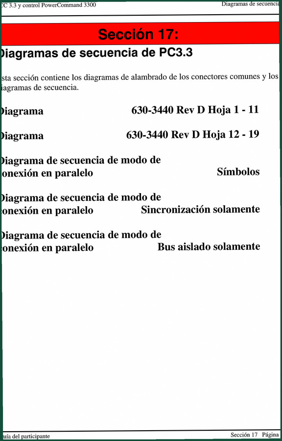
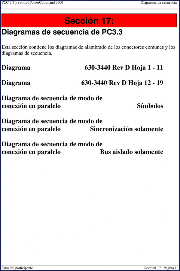
The manual opens with Section 17 – Diagramas de secuencia de PC3.3. That means sequence diagrams for the PowerCommand 3.3 controller. These are not generic. They show the exact order of events during startup, transfer, and shutdown. Page 1 lists the drawing set: 630-3440 Rev D, sheets 1 through 11 for common connector schemes, then sheets 12 through 19 for parallel mode and bus isolated operation. Each sheet is a standalone wiring diagram with connector pin callouts. You will see the PCC-002 baseboard connections, ECM engine connection details, and hydro-mechanical engine connection sheets. If your genset uses a mechanical governor, sheet 3 is the one you need. If it is an electronic engine, sheet 2. The manual does not blur the two together like aftermarket junk does.
Common Connector Scheme – Why Pinouts Matter
Page 3 of the PDF shows the wiring diagram index for the PCC common connector scheme. This index tells you exactly which sheet to pull for your specific PowerCommand version – 1.1/1.2, 2.2/2.3, or 3.3. For the PC3.3, you go to sheets 10 and 11 for the common connector, sheet 8 for genset connections, and sheets 12 through 15 for paralleling. I have had junior techs try to use a PC2.2 diagram on a PC3.3 because they thought “all PowerCommand is the same.” That is how you backfeed a voltage sense line and take out the AVR. This manual kills that problem cold. Every connector pin, every OEM connection, every customer connection is drawn out with the PCC part numbers called out.
Does This Manual Cover the Fuel System?
Odd question? Not if you are troubleshooting a no-start. The sequence diagrams show the run relay, crank disconnect, and fuel solenoid circuits. On sheet 14 (parallel mode sequence), you can trace the entire start sequence as the controller commands the engine to crank, checks frequency, and closes the breaker. The wiring for the fuel pump and shutoff solenoid is part of the common connector scheme on sheet 10. If you are chasing a no-crank condition on a PC3.3, start there. Verify pin J2-13 (run relay output) against your actual engine harness. The diagram gives you the expected voltage state at each step.
3 Reasons to Stick with OEM Wiring Documentation
First, the copyright on every sheet is 2007, and the revision letter (Rev D) tells you this was updated after field issues. Aftermarket repackagers strip that revision history. Second, the sheets include engineering approval blocks – a real engineer signed off on the pin assignments. Third, the document uses the same numbering as PCC service bulletins. If you ever call PCC tech support, they will ask for the sheet number from this exact drawing set. You cannot get that from a photocopy on a forum. This PDF is the same one used by PCC authorized dealers. That is the difference between a guess and a fix.
Parallel Mode, Synchronization, and Bus Isolated Sequence Diagrams
Three separate sequence diagrams exist for parallel operation. The manual draws each one: parallel mode with synchronization only, parallel mode with bus isolated only, and full parallel mode. If you are commissioning a new paralleling breaker, you need to see the exact interlock wiring between the controller and the genset breaker. Sheet 17 covers synchronization only – the controller matches frequency and phase before closing the breaker. Sheet 18 covers bus isolated operation where the breaker stays open but the engine runs at synchronous speed. Sheet 19 is the full sequence. Each one shows the binary inputs, status LEDs, and fault indicators. I have used these diagrams to trace a false synch lockout back to a corroded terminal on the voltage matching transformer. Took twenty minutes. Without the right sheet, you are replacing boards.
Audience Fit – Who Needs This in Their Toolbox
This is for anyone who touches a PowerCommand 3.3 – generator service techs, electrical contractors commissioning paralleling switchgear, and advanced DIYers who own a commercial standby set. If you are trying to install a remote annunciator or tie into a building management system, the customer connection diagrams on sheets 10 and 11 are your roadmap. The manual assumes you know how to use a multimeter and read a schematic. It does not hold your hand, but it gives you the facts. You will not find any fluff about “easy steps.” What you will find is the exact pinout for the PCC-002 baseboard, the master control board connector, and the genset interface. That is what you need to get the job done.
Source Validity – This Is Not a Reprint
The PDF file name ends with es-104311018169.pdf – that is a direct factory scan from the PCC training materials. The manual says “Guía del participante” on the bottom because it came from the original PowerCommand 3300 participant guide. This is the same document used in PCC training classes. Page 2 is intentionally left blank, exactly like the factory printed version. That is how you spot a true factory source vs. a third-party recompile. The wiring diagram index on page 3 lists every sheet with its rev letter. No reprints, no glued-together PDFs. You get the 40 pages as they were bound, including the blank pages and engineering approval signatures.
Frequently Asked Questions
- Does this cover the PowerCommand 3.1 or 3.2?
- No. The manual specifically covers the PC3.3. For 1.1/1.2 and 2.2/2.3, see sheets 2-9, but the sequence diagrams are different.
- What engine types are supported?
- Both ECM-based engines and hydro-mechanical engines. Sheet 2 covers ECM connections (J1939 data link, throttle actuator). Sheet 3 covers hydro-mechanical engines (magnetic pickup, actuator).
- Are the diagrams in color?
- They are black-and-white factory scans. Each wire is labeled with its function and terminal number. Color is not needed because the labels are unambiguous – no guessing on wire colors that fade or vary by revision.
- Can I use this to troubleshoot a no-start on my standby genset?
- Yes. Start with the sequence diagram sheets (12-15 for parallel mode) to see the crank and run relay commands. Then use the common connector scheme (sheet 10) to back-probe the controller pins. The manual shows expected voltage states at each step in the sequence.
Related Manuals
- Body Electrical Practice Electrical Wiring Diagrams”>Body Electrical Practice Electrical Wiring Diagrams
- LDV Electrics 1 Vehicle Wiring 1994 Onwards RHD”>LDV Electrics 1 Vehicle Wiring 1994 Onwards RHD
- LDV Electrics 1 Vehicle Wiring Diagrams 1987-1992″>LDV Electrics 1 Vehicle Wiring Diagrams 1987-1992
For more context on general automotive wiring principles, see Automotive Wiring”>Automotive Wiring and the Automotive Industry Overview”>Automotive Industry Overview.
Stop burning up controllers and wasting billable hours on guesswork. Access the Factory Manual now. This is the one piece of paper that will save you a $2,000 service call – and I am not exaggerating.
Additional information
| Brand | PCC |
|---|---|
| Language | English |
3 reviews for PCC PC3.3 Wiring Diagram – 40-Page Factory Electrical Guide
You may also like…
-
Sale!

2004 Acura TSX Wiring Diagram – 73-Page Factory Electrical Schematics
Original price was: $15.88.$9.99Current price is: $9.99. -
Sale!

Acura NSX 1991 Service Manual – 1420 Pages OEM
Original price was: $102.05.$65.00Current price is: $65.00. -
Sale!

Acura Integra 1998 Service Manual – 1891 Pages Factory OEM Documentation
Original price was: $31.75.$25.00Current price is: $25.00. -
Sale!

CDS 705C, 706C, 708C 1981 Parts Catalog – OEM Forklift Specs
Original price was: $61.60.$40.00Current price is: $40.00.
Related products
-
Sale!

1996 Operators Manual – International 1000-4000 Series (246 pages)
Original price was: $15.28.$9.99Current price is: $9.99. -
Sale!
International 1000-3000 Series Operators Manual – 132 Pages of OEM Specs
Original price was: $14.40.$10.99Current price is: $10.99. -
Sale!

2011 Parts Catalog – International Truck OE Parts Documentation (1786 Pages)
Original price was: $34.50.$25.00Current price is: $25.00. -
Sale!

Technical Manual – International 6.0L Power Stroke FICM Diagnostics
Original price was: $29.80.$20.00Current price is: $20.00.
James L. –
This is just what I was looking for. Instant access after checkout process. Every spec sheet is provided for PCC PC3.3. Saved my weekend project! Thank you.
David K. –
Great factory service manual. The text is searchable and well indexed. It helped me to troubleshoot my PCC PC3.3 electrical system. Saved my weekend project! Thanks.
gearhead88 –
I am very pleased with this transaction. It is very easy to read on my tablet without losing quality. A must-have for any PCC PC3.3 DIYer doing repairs. Great value for money.