
Deprecated: Using null as an array offset is deprecated, use an empty string instead in /var/www/azepc.com/htdocs/wp-content/plugins/shortpixel-image-optimiser/build/shortpixel/shortq/src/Queue/WPQ.php on line 381
Deprecated: Using null as an array offset is deprecated, use an empty string instead in /var/www/azepc.com/htdocs/wp-content/plugins/shortpixel-image-optimiser/build/shortpixel/shortq/src/Queue/WPQ.php on line 381
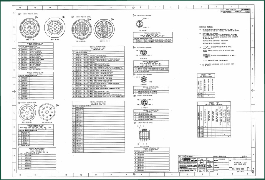
Paccar P94 Electrical Schematic – OEM Wiring Diagrams
Original price was: $23.40.$18.00Current price is: $18.00.
Factory electrical schematic for Paccar P94 engines – 15 pages of pin-out data, circuit position charts, and connector specs.
Description
You’ve seen aftermarket wiring diagrams that look like someone traced a napkin drawing after three beers. That’s not what you get with the Paccar P94 Electrical Schematic. This is the factory document — 15 pages of the actual circuit positions, connector pinouts, and terminal specs that Paccar used when they built the engine harness. No reprints, no interpretations. If you’re chasing a no-start on a P94 or an ABS fault that kills the dash, this is the paper trail that saves your Saturday.
Paccar P94 Electrical Schematic – 15 Pages of Factory Data
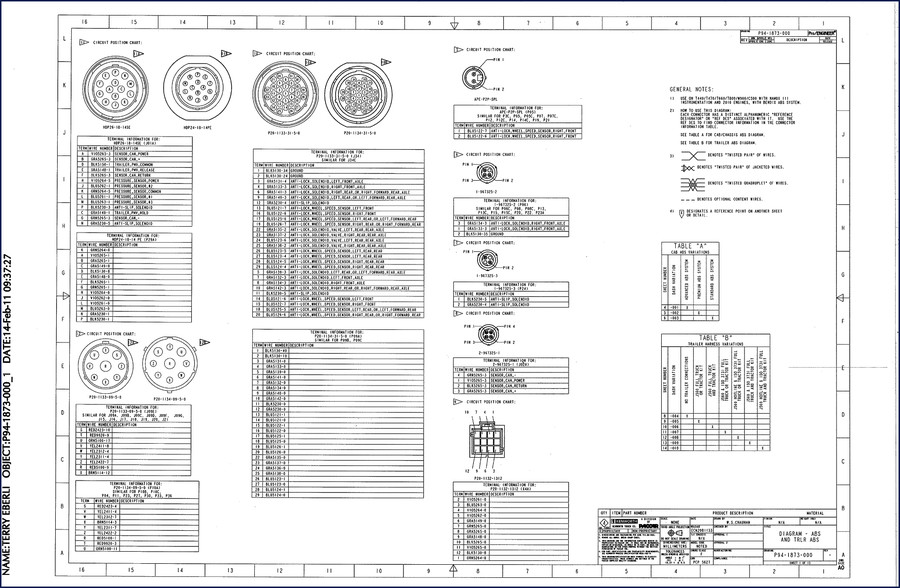
Take the 15 pages included here. They aren’t a reprint of some third-party scan. This is the original Paccar file — the same one their own techs use. Page 1 alone shows a circuit position chart and terminal information for connectors like KBP30-08-06X2 and PBS-1120-01-0-0. Wire colors, pin numbers, circuit descriptions: pump fan low, speed sensor front pump, relay coil. That level of detail is what you need when a ground wire is intermittent and the scan tool shows nothing.
Circuit Position Chart: Mapping the Harness
The circuit position chart tells you exactly where each wire lands in the connector body. The OCR excerpt shows pin rows labeled L, K, J, I, H, G with terminal sizes and wire colors. If you’ve ever chased a “BLISHED-RED” wire on a faded aftermarket copy, you know the difference. This schematic uses the factory color codes—no guessing what “dark red” means. Every pin is listed with its connector type and terminal part number.
What Does the ABS/ESP System Section Cover?
That section is critical. The general notes on page 1 state: “Check wiring for proper fit, pin, and pin pull. Check for proper pin grip. Use 3/16” diameter drill for inspection of pins. Locks if terminal is not seated properly. Use only female terminals specified.” Those aren’t suggestions. They’re the difference between a repair that holds for 100,000 miles and one that comes back on a tow truck. The ABS/ESP system section also references wiring diagram P94-1873-001, so you have a cross-reference path when the fault is in the controller.
Terminal Inspection – 3/16” Drill Test Spec
Every time I see a junior tech skip the pin pull test, I know I’ll be re-doing his work later. The factory spec here is clear: use a 3/16” diameter drill to inspect terminal grip. If the terminal doesn’t lock positively, replace it. That’s the kind of step that aftermarket docs leave out. This schematic gives you the actual terminal part numbers and tells you which connectors are used (KBP30-08-06X2, PBS-1120-01-0-0, PBS-1134-01-0-0). You don’t have to guess which pin goes where.
3 Reasons to Use OEM Wiring Diagrams Over Aftermarket
Reason one: accuracy. Aftermarket schematics often merge multiple model years into one generic drawing. This P94 schematic is specific to that engine. Reason two: torque values? No, but this isn’t a service manual — it’s an electrical schematic. What it does have is the exact pinout so you don’t backfeed a sensor circuit and fry the ECU. Reason three: safety. The ABS/ESP system section includes warnings about terminal seating that prevent shorts. For background on diesel engine fundamentals, see this Wikipedia article on diesel engines. And if you want to understand how the electronic systems integrate, this Wikipedia article on diesel engine covers the basics of modern diesel electronics.
Connector Pin Data: Reading the Terminal Tables
When you open the PDF, you’ll find tables for each connector. For example, the KBP30-08-06X2 connector lists pin 1 as BLISHED-RED (power internal), pin 2 as BLISHED-YELLOW (pump fan low), pin 3 as BLISHED-BLUE (pump fan high), and so on. The same connector has pins 7 and 8 for speed sensors. Cross-reference these with the circuit position chart to find where each wire exits. This is the level of detail that makes a 15-page schematic worth more than a 200-page aftermarket restoration.
Related manuals you might need alongside this schematic:
- Paccar 387 Electrical Schematic – Factory Wiring Guide
- Paccar 387 Model Family 2009 Electrical Schematic – Factory Wiring
- PACCAR Aftertreatment System Operator’s Manual
Frequently Asked Questions
- Does this manual include engine torque specs?
- No. This is an electrical schematic only. Torque values are in the service manual.
- How do I use the terminal information tables on page 1?
- Page 1 of the 15-page schematic contains circuit position charts and terminal tables for connectors like KBP30-08-06X2 and PBS-1120-01-0-0. Each table lists pin numbers, wire colors, and circuit descriptions (e.g., pump fan low, speed sensor front pump). The general notes tell you to use a 3/16″ drill to check pin grip, ensure proper seating, and only use specified female terminals. Cross-reference these tables with the wiring diagram in P94-1873-001 to map the entire harness.
When you need to trace a short or confirm a pinout without burning a weekend, this factory schematic pays for itself. Stop struggling with aftermarket diagrams that skip details. Click the link to access the factory manual.
Additional information
| Brand | Paccar |
|---|---|
| Language | English |
3 reviews for Paccar P94 Electrical Schematic – OEM Wiring Diagrams
You may also like…
-
Sale!

Paccar MX-13 2015 Technical Manual – Factory Programming Guide
Original price was: $67.05.$45.00Current price is: $45.00. -
Sale!
Paccar CECU3 2011 Service Manual – Multiplexed Electrical System
Original price was: $38.40.$30.00Current price is: $30.00. -
Sale!
Paccar MX-13 2013 Technical Manual – Programming Guide
Original price was: $64.80.$45.00Current price is: $45.00. -
Sale!
Paccar CECU3 2010 Service Manual – Multiplexed Electrical Diagnostics
Original price was: $74.40.$60.00Current price is: $60.00.
Related products
-
Sale!

2004 Acura TSX Wiring Diagram – 73-Page Factory Electrical Schematics
Original price was: $15.88.$9.99Current price is: $9.99. -
Sale!

2011 Parts Catalog – International 7400 SFA 6X6 – 1886 Pages of OEM Part Numbers
Original price was: $32.00.$25.00Current price is: $25.00. -
Sale!

Technical Manual – International DT 530 & HT 530 (118 Pages)
Original price was: $37.00.$25.00Current price is: $25.00. -
Sale!

1991 Electrical Schematic – 112-Page OEM Wiring Diagram for International 1000-3000 Series
Original price was: $22.75.$17.50Current price is: $17.50.
workshop_guy –
This is exactly what I needed. The scan is high-quality and well indexed. Every spec sheet is included for Paccar P94. Saves me hundreds of money.
diy_master –
This is just what I was looking for. It is easily zoomable on my phone without blur. It helped me to rebuild my Paccar P94 engine. I will definitely buy again.
Thomas B. –
This is just what I was looking for. The PDF quality is excellent. Contains clear schematics for Paccar. Saves me so much dollars.