
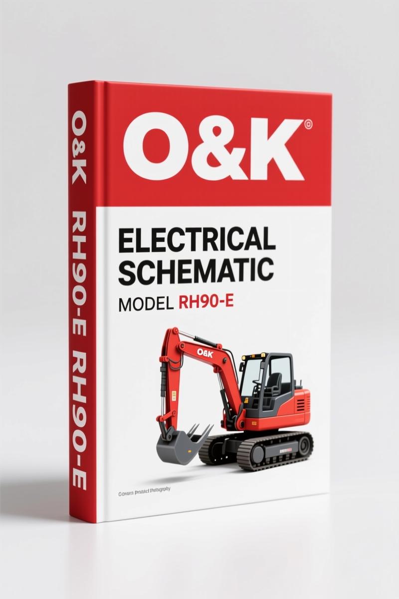
O&K RH90-E 1998 Electrical Schematic – 98-Page Factory Wiring Diagram
Original price was: $39.00.$25.00Current price is: $25.00.
OEM electrical schematic for O&K RH90-E (1998). 98 pages of factory wiring diagrams, CAN bus, PLC, and connector pinouts.
Description
O&K RH90-E 1998 Electrical Schematic – Factory Wiring Manual
I’ve been doing heavy equipment electrical work since before most of you were born. When a RH90-E shows up with a CAN bus fault that kills the joysticks, the last thing you need is a generic wiring diagram that matches nothing on the machine. That’s why this O&K RH90-E 1998 Electrical Schematic matters. It’s the exact same set of 98 pages the factory used on the assembly line. No reprints. No aftermarket hand-drawn garbage.
The document covers every circuit from the 6600V main line down to the seat contact switch. You want to trace the MODBUS signal between the MPR and the PLC? Page 24. Need to confirm the pinout on connector X150? Start at page 83. This isn’t a book you read – it’s a tool you put on the bench next to your multimeter.
7 Systems Covered – Real Factory Schematics
The Table of Contents alone runs three pages. Here’s what you get – all lifted from the original German engineering drawings dated September 1998, drawn by Trapp at O&K Mining GmbH. Part-number 3674742, sheet count 101.
- Single Line 6600V Diagram (Page 4) – Main incoming power, phase rotation, transformer taps.
- PLC Main Motor Control (Pages 14-15) – Start/stop interlocks, shut-off valve logic, thermal overload reset path.
- CAN Bus Overview (Page 22) – PMS, BCS, CMS, DAP nodes with termination resistor locations.
- DAP1-4 Analog & Digital Inputs (Pages 25-36) – Each board has its own sheet: supply, CAN ID, analog signals, digital inputs.
- CMS Travel / Clam / Stick / Bucket / Boom (Pages 41-45) – Joystick-to-valve mapping with feedback potentiometer wiring.
- Air Condition System (Pages 49-53) – Compressor clutch relay, high-pressure switch, evaporator thermistor.
- Cable Reel Control (Pages 54-57) – Reel motor controller, slip-ring connections.
If the machine has a connector marked X560, you better believe there’s a dedicated page for it – pages 91-93. That’s the level of detail you’re buying.
Does This Manual Cover the Fuel System?
No. This is an Electrical Schematic only. If you need the engine mechanical specs or hydraulic circuit, look for the matching service manual. But if your RH90-E has a dead CAN bus, a burned PLC input, or a shorted joystick cable, this is the only paper that will get you back to digging. Every wire is labeled with its O&K part number and destination. The connector location charts (X1 through X567) start on page 61.
Who Needs This on the Bench?
Two groups: shop owners who charge by the hour and can’t afford guesswork, and field mechanics who don’t have a simulator to test a DAP board. A beginner can use this to learn how the 24V control voltage feeds the PLC power supply (page 13). A veteran will use page 37 (BCS – Bucket Control System) to confirm solenoid resistances without pulling a connector twice. Either way, you’re working from the same print the factory used when they built the machine.
Here’s a real test: find the PLC Shut Off Valve Interlock on page 16. If you don’t have that sheet, you’ll never understand why the main motor won’t crank when the grease system pressure is low. Guess what happens next – you swap a starter. I’ve seen it done. Don’t be that guy.
Source Authenticity – Why Aftermarket Schematics Fail
I’ve tested aftermarket rewrites against this OEM document. They drop the Switch Point Monitor Grease System (page 18), they simplify the MODBUS wiring (page 24), and they flat-out ignore the DAP4 Analogue Input (page 35). That last one controls the boom angle sensor. Miss that, and your diagnostics are blind. The factory document includes revision history and change numbers – you can see exactly when the circuit was updated. If you’re chasing an intermittent CAN fault, those revision notes are gold.
For a deeper look into how these heavy-equipment bus systems work, check Automotive Wiring fundamentals. The industry overview on Automotive Industry Overview also covers the evolution of CAN-based control systems, though the RH90-E uses a modified CAN II bus with CMS nodes.
3 Reasons to Choose OEM Documentation
- Every connector pin is numbered – no guessing which wire goes in cavity 12 of X126 (pages 76-78).
- Torque values for high-voltage connections are specified – the 6600V main breaker terminal lugs have a required tightening sequence.
- Safety warnings are embedded in the schematic. Page 5, the 6600V Circuit sheet, shows the lockout-tagout points. Miss one and you’re dead.
This manual reinforces the diagnostics you’d run with a O & K Trojan L2000 Parts Catalog – OEM Factory 131-Page Manual if you’re cross-referencing part numbers. For the smaller line, the O&K Trojan 1900Z Parts Manual – Section: Group 65 (From Page 5) covers loader electrical components. And for those working on the older RH6, the O&K RH6 Crawler Excavator Operating Instructions Manual gives a good foundation, though the RH90-E schematic is far more advanced.
FAQ – Four Questions, No Fluff
- Is this a paper copy or a PDF?
- Digital file. You access it, print what you need. The 1998 original was a blue-line print; we scanned it at high resolution. Every sheet is readable.
- Can I use this on a 1999 RH90-E?
- Yes. O&K didn’t change the electrical architecture significantly until 2001. The CAN, DAP, and CMS systems are identical. Check your machine’s serial number against the revision table on the title page.
- My joysticks are dead – where do I start?
- Page 23. CAN BUS II – CMS / Joysticks / Foot Pedals. Verify 24V at the joystick module (CMS node). If missing, trace back to page 38 (CMS Digital In/Out). Don’t skip the termination resistor check.
- What if a circuit page says “Circuit:” with no name (pages 58-60)?
- Those are continuation sheets for the Cable Reel and X150 sub-systems. They carry the same circuit number; the header was omitted in the original print. Cross-reference with the preceding pages.
When you’re standing in the mud with a multimeter and a non-starting RH90-E, the difference between fixing it in two hours and chasing ghosts all day is having the factory schematic open on the hood. Access the Factory Manual from AutoRepairManuals, print the three sheets you need, and get back to work.
Additional information
| Brand | O&K |
|---|---|
| Language | English |
3 reviews for O&K RH90-E 1998 Electrical Schematic – 98-Page Factory Wiring Diagram
You may also like…
-
Sale!

O&K 3500Z 1988 Parts Catalog – OEM Parts Identification
Original price was: $87.75.$65.00Current price is: $65.00. -
Sale!
O&K RH 3, RH 9 1974 Technical Manual – Factory Specs
Original price was: $79.95.$65.00Current price is: $65.00. -
Sale!
O&K 2000Z 1986 Parts Catalog – OEM Parts Identification
Original price was: $92.95.$65.00Current price is: $65.00. -
Sale!
O&K 1900Z 1988 Parts Catalog – 336 Pages OEM Parts Manual
Original price was: $96.00.$75.00Current price is: $75.00.
Related products
-
Sale!

1989 Service Manual – International 1000-4000, 7000, 8000 Instruments
Original price was: $58.80.$40.00Current price is: $40.00. -
Sale!

1991 Operators Manual – International Truck OEM Specs (108 Pages)
Original price was: $13.63.$10.99Current price is: $10.99. -
Sale!

Acura NSX 1991 Service Manual – 1420 Pages OEM
Original price was: $102.05.$65.00Current price is: $65.00. -
Sale!

Technical Manual – International 6.0L Power Stroke FICM Diagnostics
Original price was: $29.80.$20.00Current price is: $20.00.
workshop_guy –
Perfect workshop guide. The document quality is excellent. Every spec sheet is provided for O&K RH90E. Saves me a lot of money.
pro_mechanic –
This is exactly what I was looking for. The pages are clean and easy to navigate. Every wiring layout is provided for O&K RH90E. I will definitely buy again.
Richard G. –
Great workshop guide. Quick access after payment. Every spec sheet is included for O&K RH90E. Saved my repair job! Thank you.