
Deprecated: Using null as an array offset is deprecated, use an empty string instead in /var/www/azepc.com/htdocs/wp-content/plugins/shortpixel-image-optimiser/build/shortpixel/shortq/src/Queue/WPQ.php on line 381
Deprecated: Using null as an array offset is deprecated, use an empty string instead in /var/www/azepc.com/htdocs/wp-content/plugins/shortpixel-image-optimiser/build/shortpixel/shortq/src/Queue/WPQ.php on line 381
Navistar 5000i, 9200i, 9400i, 9900i, 9100 2002 Wiring Diagram – 93 Pages
Original price was: $26.40.$20.00Current price is: $20.00.
93-page OEM wiring diagram for 2002 Navistar 5000i, 9200i, 9400i, 9900i, 9100 — connector composites, gauge cluster pinouts, and circuit diagrams.
Description
Navistar 5000i, 9200i, 9400i, 9900i, 9100 2002 Wiring Diagram
You’ve got a 2002 Navistar with an electrical problem. Maybe the left gauge cluster is dead, or the trailer ABS warning won’t clear. Without the right Navistar 5000i, 9200i, 9400i, 9900i, 9100 2002 Wiring Diagram, you’re guessing which wire goes where. I’ve watched guys replace a whole dash harness because they misread a third-party drawing. That’s money down the drain and a fire risk. This OEM document from International Truck and Engine Corporation gives you the actual factory circuit diagrams for chassis built after November 4, 2002. 93 pages of connector pinouts, gauge cluster layouts, and revision-controlled schematics. No aftermarket reprint – original factory print.
Connector Composites – Chapter 13 Breakdown
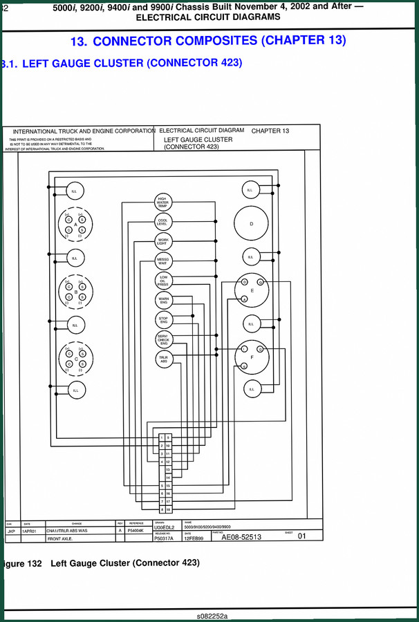
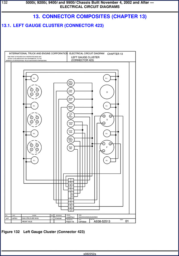
Chapter 13 is the meat of this manual. It’s labeled “CONNECTOR COMPOSITES” and covers the left gauge cluster connectors on your 5000i, 9200i, 9400i, 9900i, or 9100. Connector 423 and Connector 424 are shown in full detail with cavity numbers, signal names, and wire color codes. You’ll see exactly which pin carries HIGH WATER TEMP, LOW OIL PRESS, ENG STOP, WORK LIGHT, and all the other dash indicators. Each drawing includes the part number (AE08-52513), sheet numbers, revision dates, and release numbers. That kind of traceability keeps you out of trouble.
Left Gauge Cluster Connector 423: Factory Pin Assignments
Connector 423 is your primary interface for warning lights and engine status signals. The diagram labels each cavity with the signal name and the connector face orientation. Need to know which wire is for the ENG SERV/CHECK light? Cavity 8. Want the TRAILER ABS signal? Cavity 11. The drawing also shows the connector shell layout with all 18 positions. If you’re adding an aftermarket accessory, this is the page that keeps you from backfeeding voltage into the ECM. Trust the factory drawing, not a generic pinout from a forum.
Get the Right Pinout from Connector 424
Connector 424 handles the duplicate or alternative signals for some of the same indicators. Compare Connector 423 and 424 side by side – you’ll see that COOL LEVEL and HIGH WATER TEMP appear on both, but with different cavity assignments. That’s typical on these Navistar chassis. If you swap connectors without looking at the diagram, you’ll have a gauge cluster that lights up like a Christmas tree. Page 133 (in the original) shows Connector 424 with its 12 pins and the same signal set. Use this chapter to verify continuity before you clip anything.
Who Needs This Wiring Diagram?
If you own a 2002 International 5000i, 9200i, 9400i, 9900i, or 9100 and you do your own electrical work, this is the only wiring diagram you should trust. Fleet mechanics, mobile repair guys, and serious DIYers who want to avoid downtime will use these diagrams to troubleshoot sensor faults, ABS issues, or gauge failures. The manual assumes you have a basic multimeter and know how to read a schematic – it doesn’t hold your hand. But it gives you the real pinout every time. Pair it with a Navistar VV 1100, VV 1500 2003 Operators Manual – OEM Factory Specs if you need the operator-level info.
3 Reasons to Choose Factory OEM Documentation
First, the diagrams are dated and revision-controlled. You can see exactly when the drawing was last updated (11APR01 for some sheets). Aftermarket wiring diagrams often mix years and models. Second, these use the actual connector part numbers from Navistar – not generic symbols. Third, the signal names match the factory diagnostic software. When you see “CNA1//TRLR ABS WAS” on the drawing, that’s the exact signal the ECM expects. No translation errors. That’s why I won’t touch a third-party electrical manual for these trucks. Learn more about Automotive Wiring best practices on Wikipedia, but always reference the factory source.
Left Gauge Cluster – Gauge Information on Page 134
The third page of Chapter 13 (original page 134) lists the actual gauge functions: ENGINE WATER TEMPERATURE, ENGINE OIL PRESSURE, VOLTMETER, AIR APPLICATION (optional), PYROMETER (optional), and ENGINE OIL TEMPERATURE. Below that are notes: “VIEWED FROM REAR OF HOUSING” and “NUMBERS IN BOXES CORRESPOND TO CAVITY NUMBERS IN CLUSTER.” This is the kind of detail that saves you from installing a gauge backwards. For diagnostics, see also the Radio Remote Boom Control System Operator Manual and Navistar MaxxForce 11 & 13 Diagnostics Manual for engine-side troubleshooting.
FAQ
- Does this wiring diagram cover the 9100 model?
- Yes. The manual explicitly includes 9100 chassis along with 5000i, 9200i, 9400i, and 9900i.
- What if my chassis was built before November 4, 2002?
- These diagrams are clearly marked “Chassis Built November 4, 2002 and After.” Earlier chassis may have different connector layouts and pin assignments. While some circuits might carry over, you risk mismatched signals if you use these diagrams on a pre-November 2002 truck. Always verify the build date on your vehicle identification plate. If you need the earlier version, contact Navistar directly or check our other OEM manual listings that cover pre-2002 models. The connector numbers (423, 424) are reused across years, but the cavity assignments changed. Do not assume compatibility.
Whether you’re repairing a gauge cluster, adding a work light, or tracing an intermittent short, the only reliable source is the factory print. Don’t waste time on copied schematics that blur signals. Access the Factory Manual now and keep it on your tablet or print it for the toolbox. For broader industry context, see Automotive Industry Overview on the evolution of heavy-truck electrical systems.
Additional information
| Brand | Navistar |
|---|---|
| Language | English |
3 reviews for Navistar 5000i, 9200i, 9400i, 9900i, 9100 2002 Wiring Diagram – 93 Pages
You may also like…
-
Sale!
Navistar MaxxForce 11, MaxxForce 13 2013 Service Manual – 543 Pages OEM Specs
Original price was: $86.40.$60.00Current price is: $60.00. -
Sale!
Navistar MaxxForce 7 2014 Service Manual – 499 Pages OEM Specs
Original price was: $66.50.$50.00Current price is: $50.00. -
Sale!
Navistar MaxxForce 11 2011 Service Manual – 490 Pages Factory Spec Data
Original price was: $47.12.$38.00Current price is: $38.00. -
Sale!
Navistar MaxxForce 11, MaxxForce 13 2013 Diagnostics Manual
Original price was: $75.50.$50.00Current price is: $50.00.
Related products
-
Sale!

1991 Operators Manual – International Truck OEM Specs (108 Pages)
Original price was: $13.63.$10.99Current price is: $10.99. -
Sale!

2005 Parts Catalog – International NGD 3.0 L Engine (77 pages)
Original price was: $44.70.$30.00Current price is: $30.00. -
Sale!

2006 Service Manual – International DT 466E, 530E Diesel Engine
Original price was: $67.50.$50.00Current price is: $50.00. -
Sale!

1992 Electrical Schematic – International 1000/3000/4000/2554 OEM Wiring Diagrams (132 Pages)
Original price was: $26.40.$20.00Current price is: $20.00.
James L. –
I am so happy with this purchase. The text is searchable and easy to navigate. Every torque spec is included for Navistar 5000i,. Highly recommended for mechanics.
Richard G. –
I am so happy with this manual. It is easily zoomable on my phone without blur. It guided me to fix my Navistar 5000i, transmission. Saved my repair job! Thank you.
workshop_guy –
Superb resource! The text is searchable and easy to navigate. Every torque spec is included for Navistar 5000i,. Saved my weekend project! Thanks.