
Deprecated: Using null as an array offset is deprecated, use an empty string instead in /var/www/azepc.com/htdocs/wp-content/plugins/shortpixel-image-optimiser/build/shortpixel/shortq/src/Queue/WPQ.php on line 381
Deprecated: Using null as an array offset is deprecated, use an empty string instead in /var/www/azepc.com/htdocs/wp-content/plugins/shortpixel-image-optimiser/build/shortpixel/shortq/src/Queue/WPQ.php on line 381
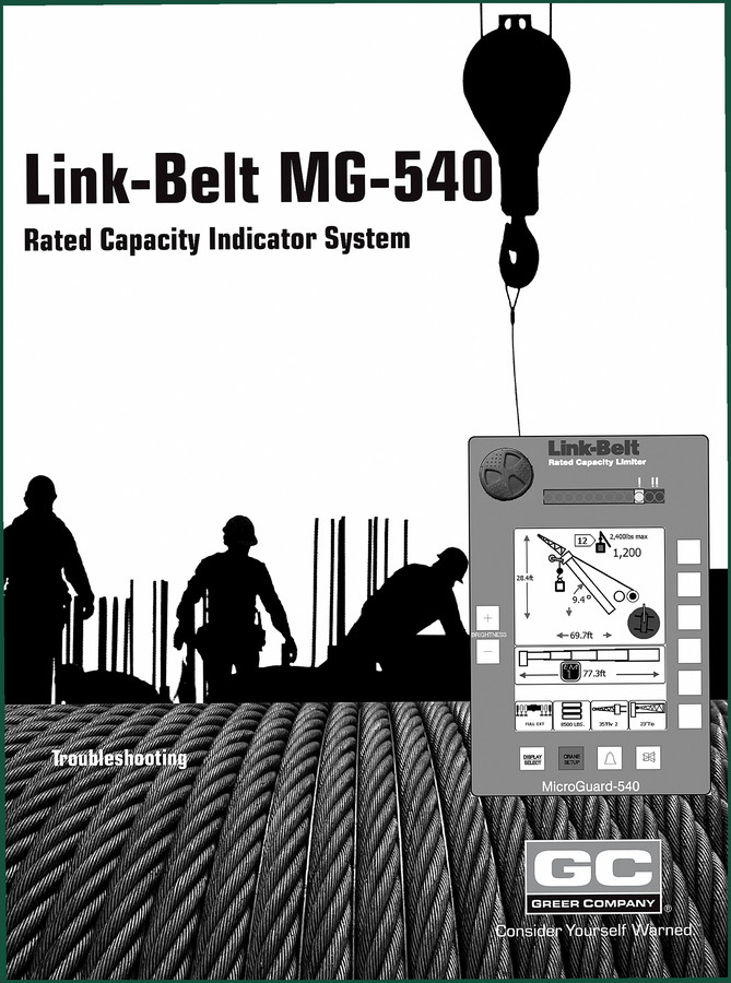
Link-belt MG-540 Troubleshooting Manual – 54-Page Factory Diagnostic Guide
Original price was: $36.00.$30.00Current price is: $30.00.
54-page OEM troubleshooting manual for Link-belt MG-540 Rated Capacity Indicator. Covers system self-test, fault codes, extension reel, ATB, and swing sensor diagnostics.
Description
Link-belt MG-540 Troubleshooting Manual
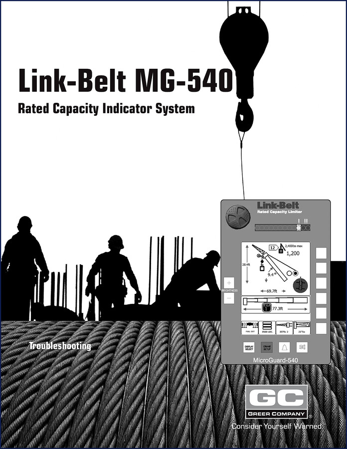
If your MG-540 display is throwing erratic load percentages or the angle sensor won’t hold calibration, you’re wasting billable hours guessing which wire to probe. That’s why this Link-belt MG-540 Troubleshooting Manual belongs on your bench. It’s 54 pages of factory procedures – not some aftermarket reprint that skips steps. I’ve seen guys replace a computer unit because they didn’t check the extension reel drive voltage first. This manual gives you the order of operations so you don’t swap parts you don’t need.
The TOC opens with Where To Go For Help, then Required Tools. Page 2 lists what you’ll need: a digital multimeter, a calibrated weight set, and a T10 Torx driver. Then Number Conversion (critical if you’re switching between metric and imperial) and Number Entry – the keypad sequence matters. The Display section walks through the LCD layout and what each icon means. Calibration Mode comes next, followed by System Overview and a Problem Finder that splits into Self-Test, Display Console Problems, Fault Reporting, and No Fault Code Problems.
Rated Capacity Indicator System: What This Manual Covers
The manual breaks down the entire RCI system into nine serviceable subsystems. Computer Unit – layout, replaceable parts, pressure sensors, and full replacement procedure. Display Console – checking the display, removal/installation, and the Compact Flash Card. Remote Load Indicator – overview and validation checks. Extension Reel – cable layering, drive voltage, boom extension sensor voltage, angle sensor pendulum and setup. Anti Two-Block – switch configurations and circuit tests. Power, Kickout, and Boom Mode Outputs. Swing Sensor – drive voltage, output voltage, resistance, and setup checks. Every section has voltage specs and diagnostic flows.
9 Systems Covered from Computer Unit to Swing Sensor
Each subsystem gets its own chapter with exact test points. The Computer Unit chapter shows the board layout and which connectors carry power versus signal. The Extension Reel chapter requires you to check the reel-off cable layering before you do any electrical tests – a common oversight that causes false extension readings. The Anti Two-Block section explains the ATB switch configurations (normally open vs. normally closed) and how to test the circuit continuity. The Swing Sensor chapter gives resistance values and a setup procedure that aligns the pendulum. Without these pages, you’re flying blind.
Does This Manual Include Calibration Mode Procedures?
Yes. Calibration Mode is detailed on page 6. It walks you through the angle sensor and extension sensor calibration, including the required weight set and bubble level. The system will reject any value that doesn’t match the factory sequence. For understanding how the calibration values are transmitted, the principles are analogous to a Manual Transmission data stream – pulse width and voltage thresholds matter.
Get the Right Specs: Torque Values and Voltage Checks
This manual lists drive voltages for every sensor – extension, angle, swing. It also gives torque specs for mounting bolts. The computer unit housing is plastic; over-torque the fasteners and you crack the cover. The extension reel drive voltage check: set your multimeter to DC volts, probe between pins 1 and 2, expect 5.0 ±0.2 V. The swing sensor resistance check is similar to troubleshooting a Manual Transmission solenoid coil – you need to see within spec or replace.
Extension Reel Troubleshooting: What the Manual Reveals
The Extension Reel chapter is worth the price alone. It starts with checking the reel-off cable layering – if the cable overlaps, the encoder counts double. Then you measure the extension sensor drive voltage, then the boom extension sensor voltage. Angle sensor pendulum check: if the pendulum sticks at 9°, your boom angle is off by that much. The ATB function tests the circuit with the switch in each configuration. These steps prevent false kickouts that shut down the crane.
Frequently Asked Questions
- What tools do I need for troubleshooting the MG-540?
- Digital multimeter, calibrated weight set, T10 Torx driver.
- Does this manual cover fault codes?
- Yes. The Problem Finder chapter includes Fault Reporting And Fault Codes. It lists the fault codes for the display console and computer unit, plus a section on “No Fault Code” problems where the symptoms exist but no code is set. It also covers System Self-Test and Display Console Problems. The diagnostic logic helps you isolate intermittent issues. For example, if the display goes blank but has power, the manual guides you through the compact flash card check and display console removal.
- How many pages is this manual?
- 54 pages of factory troubleshooting content.
- Can I use this manual for calibration?
- Yes. Calibration Mode is covered on page 6 with full step-by-step for angle and extension sensor setups.
Related Manuals
- Link-Belt MG-534 Rated Capacity Indicator System Troubleshooting
- Link-Belt Trouble Diagnosis System Service Text
- Link-Belt DS 350 Rated Capacity Limiter System
This manual keeps you from chasing ghosts in the wiring. If you work on Link-Belt cranes, you need the factory data to trust the readings. Access the Factory Manual and get the diagnostics right the first time.
Additional information
| Brand | Link-belt |
|---|---|
| Language | English |
3 reviews for Link-belt MG-540 Troubleshooting Manual – 54-Page Factory Diagnostic Guide
You may also like…
-
Sale!

Link-belt 248 HSL Service Manual – Factory Crane Procedures
Original price was: $86.80.$70.00Current price is: $70.00. -
Sale!

Link-belt 330LX 2002 Service Manual – Factory Specs for Crawler Excavator
Original price was: $96.85.$65.00Current price is: $65.00. -
Sale!

Link-belt DS350, 1225, 1229 1998 Troubleshooting Manual – Factory Error Codes & Wiring
Original price was: $102.05.$65.00Current price is: $65.00. -
Sale!

Link-belt L130 Service Manual – 652 Pages of Factory Specs
Original price was: $85.80.$65.00Current price is: $65.00.
Related products
-
Sale!

1991 Electrical Schematic – 112-Page OEM Wiring Diagram for International 1000-3000 Series
Original price was: $22.75.$17.50Current price is: $17.50. -
Sale!

2011 Parts Catalog – International Truck OE Parts Documentation (1786 Pages)
Original price was: $34.50.$25.00Current price is: $25.00. -
Sale!

Technical Manual – International 6.0L Power Stroke FICM Diagnostics
Original price was: $29.80.$20.00Current price is: $20.00. -
Sale!
International 1000-3000 Series Operators Manual – 132 Pages of OEM Specs
Original price was: $14.40.$10.99Current price is: $10.99.
James L. –
Perfect OEM spec sheet. The pages are clean and well indexed. Every spec sheet is provided for Link-belt MG540. I will recommend this shop to others.
Charles W. –
I am so happy with this manual. The scan is high-quality and easy to navigate. Every torque spec is provided for Link-belt MG540. Saves me a lot of dollars.
Richard G. –
Excellent workshop guide. Instant access after checkout process. It helped me to troubleshoot my Link-belt MG540 electrical system. I will definitely buy again.