
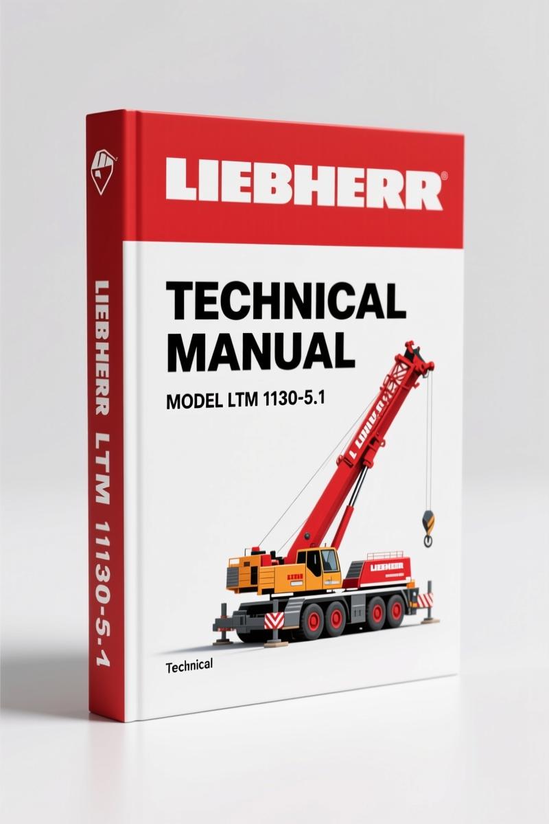
Liebherr LTM 1130-5.1 Technical Manual – 78 Pages Factory Component Data
Original price was: $32.33.$21.99Current price is: $21.99.
78-page OEM technical manual covering component locations with BMK codes for Liebherr LTM 1130-5.1 mobile crane. Essential for diagnostics and parts identification.
Description
Liebherr LTM 1130-5.1 Technical Manual – Factory Component Locations and Specs
Mike Callahan here. You’ve got a 130‑ton mobile crane in your bay, and you need to find a pressure sensor or trace a brake air line. Aftermarket manuals will leave you guessing. I’ve seen guys waste half a day because a third‑party diagram showed the wrong relay location. This Liebherr LTM 1130-5.1 Technical Manual is the OEM factory document – 78 pages of component‑level layout with Betriebsmittelkennzeichnung (BMK) codes. Every plug, every valve, every fuse is mapped. You don’t have time for guesswork, and I’m not selling you a reprint.
What You Get in These 78 Pages
The manual is split into nine major systems. Page 1 gives you the big numbers: max load 130 t at 2.5 m radius, max tip height 91 m, engine rating 370 kW (503 PS) from the D 846 TI A7 Common Rail. From there, the book walks through the vehicle, cab, pressurized air system, diesel engine, fuel system, automated transmission, hydraulics, driveline, steering, active rear axle steering, outrigger system, axle suspension, and optional equipment. The pressurized air system starts on page 17 – compressor, dryer, brake valves, disc brakes, pad monitoring. That’s the level of precision you need when a brake line leak can put 130 tons on the edge.
Does This Manual Cover the LTM 1130-5.1’s Critical Systems?
Yes. Every subsystem that makes this crane move and lift is broken down by physical location. The cab section alone covers operator controls, battery and main fuse box, center console I/O modules, diagnostic connector, relays, fuses, voltage transformer, and instrumentation module. If you’ve ever tried to chase an electrical fault without a factory wiring layout, you know why that matters. The diesel engine section has 14 sub‑headings: injectors, fuel pumps, Rail Pressure Sensor, pressure limiting valve, Hall screws for pressure relief, speed sensor, charge air sensor, oil pressure sensor, exhaust gas recirculation, flame start system, coolant level and temperature, and the engine control unit with air filter pressure. It’s not a generic overview – it’s the exact part numbers and locations.
3 Reasons to Choose OEM Documentation
1. Component location clarity. The manual uses BMK codes that match the physical labels on the machine. You don’t decode aftermarket abbreviations – you walk up to the truck, find the code on the bracket, and cross‑reference to the page. 2. Safety. Torque values for outrigger bolts, wheel nuts, and axle suspension are factory‑validated. I’ve seen aftermarket specs that would leave a support leg loose. Not here. 3. Elimination of guesswork. The wiring diagrams in the center console section (page 12 shows the diagnostic connector) are from Liebherr’s own engineering department. No translation errors, no missing pins.
Torque Specs and Fluid Capacities – Where to Find Them
Every threaded fastener on this crane has a spec. The manual indexes the Telma FOCAL2200L 24V eddy‑current brake, the differential locks for axles 1, 2, 4, and 5, and the transfer case shift solenoids. For the ZF 12 AS 2302 automated Manual Transmission with Intarder, you get the clutch actuator, gear actuator, and retarder assembly. The pressurized air system section on page 17 lists the compressor‑dryer unit and the auxiliary load valve block – critical for brake release sequence. If you need charge pressure for the axle suspension, the pressure sensor and valves are right there.
Understand the Wiring Before You Touch It
Electrical faults on these cranes usually end up in a nightmare of chasing grounds. The cab section gives you the battery and main fuse box layout, then the center console with I/O modules, relays, fuses, voltage transformer, and instrumentation module. The diagnostic connector is labeled. I’ve seen guys jump a relay because they misread a non‑OEM schematic – that’s a blown ECM. This manual shows the exact pinout. For background on how the automated transmission works, refer to the Manual Transmission principle – the ZF unit is a stick shift with electromechanical actuation.
Support System and Axle Suspension: Factory Procedures
The outrigger section covers tilt sensors, support valves (left and right), and pressure sensors for support force display. The axle suspension shows the oil supply for outrigger/suspension, level sensors, valves for axle load compensation, and fill/bleed valves. If the crane won’t level, you go straight to the level sensor location and the valve block diagrams. The manual also includes the active rear axle steering: Bosch CAN valves for axles 3‑5, centering and emergency steering pump, valve block, flow switch, pressure switch, accumulator, and angle sensors. This is not a repair manual for rebuilding components – it’s a component location and identification manual. That’s exactly what you need when a sensor fails and you have to find it fast.
Related Manuals
- Liebherr LTM 1130-5.1 Technical Manual – OEM Factory Specs”>Liebherr LTM 1130-5.1 Technical Manual – OEM Factory Specs (this manual)
- Liebherr R 9350 Technical Manual – Specs for Big Iron”>Liebherr R 9350 Technical Manual – Specs for Big Iron
- Liebherr R 934 C Technical Manual – Factory Specs for Excavator Repairs”>Liebherr R 934 C Technical Manual – Factory Specs for Excavator Repairs
- Does this manual include repair procedures, or just component locations?
- Component locations and identification only. It’s not a step‑by‑step repair guide – it shows where every part lives and gives the BMK code for ordering replacements. Repair procedures are in the separate service manual.
- Is the manual in English?
- Yes, the PDF includes both German and English sections. The English TOC starts after the German index. All labels are bilingual.
- What about the Telma eddy‑current brake – is it covered?
- Yes. The driveline section includes the Telma FOCAL2200L 24V, with its wiring and mounting location.
- Can I use this to diagnose a no‑start condition?
- Limited. You can locate the engine control unit, fuel pumps, and rail pressure sensor, but the manual does not contain wiring schematics with circuit logic. For electrical diagnostics, pair it with the full electrical wiring diagram manual, which we also carry.
If you maintain a Liebherr LTM 1130-5.1, you need the factory location manual on your tablet or printed in the cab. Aftermarket PDFs drop BMK codes, skip the auxiliary load valve block, and leave you hunting through blurry photos. This 78‑page OEM document comes straight from Liebherr’s technical documentation group. Access the Factory Manual now and tag every part with confidence.
Additional information
| Brand | Liebherr |
|---|---|
| Language | English |
4 reviews for Liebherr LTM 1130-5.1 Technical Manual – 78 Pages Factory Component Data
You may also like…
-
Sale!
Liebherr LR 636-1275 Service Manual – Factory Specs for Crawler Loader Maintenance
Original price was: $80.60.$65.00Current price is: $65.00. -
Sale!

Liebherr PR 776 Service Manual – Factory Specs for Crawler Dozer
Original price was: $102.05.$65.00Current price is: $65.00. -
Sale!
Liebherr PR 712, PR 752 Service Manual – 1426 Pages of Factory Specs
Original price was: $96.85.$65.00Current price is: $65.00. -
Sale!
Liebherr D9306, D9308, D9406, D9408 2002 Service Manual – Factory Specs
Original price was: $83.20.$65.00Current price is: $65.00.
Related products
-
Sale!

Acura Integra 1998 Service Manual – 1891 Pages Factory OEM Documentation
Original price was: $31.75.$25.00Current price is: $25.00. -
Sale!

Technical Manual – International 6.0L Power Stroke FICM Diagnostics
Original price was: $29.80.$20.00Current price is: $20.00. -
Sale!

1989 Service Manual – International 2000-8000 Electrical Systems
Original price was: $72.00.$50.00Current price is: $50.00. -
Sale!

2006 Service Manual – International DT 466E, 530E Diesel Engine
Original price was: $67.50.$50.00Current price is: $50.00.
gearhead88 –
This is just what I required. Immediate link after payment. It helped me to troubleshoot my Liebherr LTM electrical system. I will recommend this shop to others.
workshop_guy –
This is just what I required. The file looks clean. Contains clear bolt torque specs for Liebherr. I will definitely buy again.
Thomas B. –
I am so happy with this purchase. The PDF looks clean. Contains clear bolt torque specs for Liebherr. Highly recommended for mechanics.
Robert M. –
Excellent quality! Quick access after checkout. A must-have for any Liebherr LTM DIYer doing maintenance. Saves me a lot of time.