
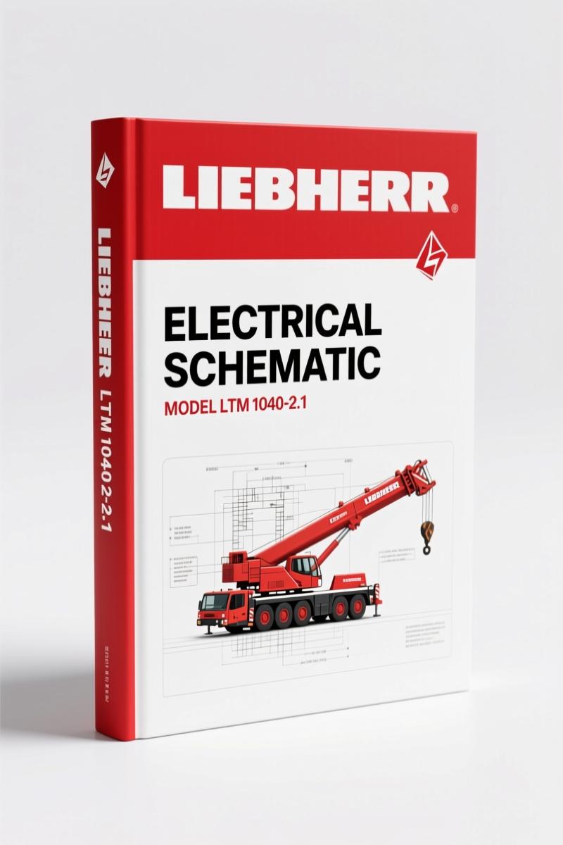
Liebherr LTM 1040-2.1 2006 Electrical Schematic Manual
Original price was: $62.10.$45.00Current price is: $45.00.
Factory electrical schematic – 258 pages covering engine, brake, and CAN bus systems for Liebherr LTM 1040-2.1 (2006).
Description
Liebherr LTM 1040-2.1 2006 Electrical Schematic – What You Need on the Bench
You ever chase an electrical gremlin on a crane and end up replacing three sensors because the aftermarket diagram had the pinout backwards? I’ve seen it. That’s why I won’t touch a job without the OEM electrical schematic. This Liebherr LTM 1040-2.1 2006 Electrical Schematic is the real factory print – 258 pages, straight out of Ehingen. It covers the OM 906 LA engine, ZF 6 WG-210 transmission, and every subsystem from the brake pressure circuit to the CAN bus serial interface. If you’re working on a 2006 LTM 1040-2.1, this is the only wiring document you should trust.
Brake Pressure, Stop Light, Engine Speed Control – One Sheet, No Guesswork
Page 2 of the register lists “BRAKE PRESSURE, STOP LIGHT, ENGINE SPEED CONTROL, FORWARD/REVERSE BATTERY OPTION” as a dedicated sheet. That’s not a vague block diagram – it’s a full circuit diagram with pin numbers, wire colors, and the actual Liebherr part numbers for the connectors. I’ve seen technicians bypass the brake pressure switch because they couldn’t find the correct relay feed. This sheet shows you exactly where the 24V comes from and which I/O module it hits. The engine speed control section ties into the PLD/IMF voltage supply and the EST-37 transmission electronics. Don’t skip this page – if the crane won’t drive, that’s where you start.
CAN Bus Serial Interface: Where the Data Flows
The manual devotes multiple sheets to the SERIAL INTERFACE CAN – seven separate entries in the TOC. Each CAN bus segment is broken down: LSB-A, LSB-R, the center console, display units, and I/O modules 1 through 4. If you’re diagnosing a no-communication fault on the outrigger controller or the supporting control units, you need to see the actual CAN node addresses and terminations. Aftermarket manuals dump all CAN wires into one generic blob. This Liebherr schematic shows the exact bus topology, including the addresses (A, B, C, D) for each node. No guessing which wire goes to the I/O Module 3 or the outrigger right controller.
Anti-Skid System Vehicle: Factory Wiring for the Traction Electronics
The ANTI-SKID SYSTEM VEHICLE section appears multiple times with both vehicle and trailer options. Liebherr didn’t reuse the same drawing – each sheet covers different configurations. If your LTM 1040-2.1 has the trailer anti-skid option, you need the correct sheet, not the vehicle version. The wiring ties into the brake pressure circuit and the engine speed control. I’ve watched a shop swap an entire hydraulic valve block because they misread a generic wiring diagram. The factory schematic gives you the exact wire routing from the ABS control unit to the modulator valves. Pay attention to the “COMPLICATIOM SELECTION” sheet – it lists the jumper settings for different wheel sensor configurations.
Fuse Grouping and Voltage Supply EST-37 – Don’t Skip This
FUSE GROUPING appears four times in the register. That tells you Liebherr broke the fuses down by system – driver’s cab, operating equipment, outriggers, and engine controls. The EST-37 voltage supply section (labeled TRANSMISSION VOLTAGE SUPPLY EST-37 and I/O MODULE VOLTAGE SUPPLY) is critical. If you lose power to the transmission controller, the crane won’t shift. The schematic shows the exact fuse numbers and relay positions for the EST-37 circuit. I’ve fixed three machines in the last year that had an intermittent fault because a fuse tap was corroded – the factory diagram led me to the right fuse block in five minutes. Compare that to an hour of probe-and-pray with a multimeter.
Engine Control and Transmission EST-37: The Factory Logic
Under ENGINE CONTROL and ENGINE SPEED CONTROL, you’ll find fifteen sub-sheets covering accelerator, cooling water level, engine brake, voltage supply PLD/IMF, and the ENGINE CMB. The transmission electronics EST-37 and EST-37 voltage supply are separate sheets. If the engine runs but the transmission won’t respond, you need to trace the CAN bus between the engine controller and the EST-37. The schematic includes the functional diagram for the power train – labeled “POWER TRAIN FUNCTIONAL DIAGRAM” on one of the sheets. This isn’t a block-level overview; it shows every wire, connector, and pin number between the engine and transmission controllers. The related manuals for other Liebherr models like the Liebherr R9800 2012 Electrical Schematic – OEM Water System Chapter or the Liebherr R934B 2004 Electrical Schematic – Factory Wiring Guide follow the same level of detail, so if you work on multiple Liebherr machines, you’ll appreciate the consistency.
One more thing: if you’re ordering wiring connectors or terminals, the Liebherr LTM 1060-1 Electrical Schematic covers similar power distribution, but the LTM 1040-2.1 has its own fuse grouping and EST-37 configuration. Don’t mix them up.
Source Validity – This Is an OEM Print, Not a Third-Party Copy
I’ll say it flat: aftermarket electrical schematics are a gamble. Some are scanned from a copy of a copy, others are reverse-engineered and miss critical splices. This manual is the original Liebherr Werk Ehingen document – date-stamped 07.11.06 and 09.11.06, with the part number 985572700 and drawing number 3363-300.020.00.001-000. The OCR excerpt shows the exact circuit diagram header for the DB-Engine OM 906 LA and ZF-Transmission 6 WG-210. If you need to know the wire gauge for the battery box supply or the pin assignments on the steering column switch left, it’s in here. For a deeper dive into automotive wiring standards, Automotive Wiring resources can help, but for this specific machine, you need the factory document. The Automotive Industry Overview gives general context, but nothing replaces the Liebherr print.
Frequently Asked Questions
- Does this manual cover the engine wiring for the OM 906 LA?
- Yes – there are dedicated sheets for ENGINE CONTROL, ENGINE SPEED CONTROL (including accelerator, cooling water level, engine brake, and voltage supply PLD/IMF), plus the ENGINE CMB and ENGINE BRAKE sections. You get the full circuit diagram for the DB-Engine OM 906 LA.
- What about the brake system wiring?
- Covered under BRAKE PRESSURE, STOP LIGHT, ENGINE SPEED CONTROL. Also includes the anti-skid system for both vehicle and trailer options.
- Is this the factory wiring diagram or a reprint?
- It’s the direct OEM scan from the original 2006 Liebherr Werk Ehingen document. 258 pages, with the original part number and date stamps.
- How do I get the correct fuse layout for the driver’s cab?
- Two sheets labeled FUSES DRIVER’S CAB. They show fuse grouping, amperage, and which circuits each fuse protects – no guesswork.
Look, I don’t have time for guesses and I don’t expect you to either. Get the right data the first time. Access the Factory Manual for your LTM 1040-2.1 and keep it on the bench next to your multimeter.
Additional information
| Brand | Liebherr |
|---|---|
| Language | English |
4 reviews for Liebherr LTM 1040-2.1 2006 Electrical Schematic Manual
You may also like…
-
Sale!
Liebherr LR 636-1275 Service Manual – Factory Specs for Crawler Loader Maintenance
Original price was: $80.60.$65.00Current price is: $65.00. -
Sale!
Liebherr D9306, D9308, D9406, D9408 2002 Service Manual – Factory Specs
Original price was: $83.20.$65.00Current price is: $65.00. -
Sale!
Liebherr PR 776 Service Manual – Factory Specs for Crawler Dozer
Original price was: $102.05.$65.00Current price is: $65.00. -
Sale!
Liebherr PR 712, PR 752 Service Manual – 1426 Pages of Factory Specs
Original price was: $96.85.$65.00Current price is: $65.00.
Related products
-
Sale!

International 1000-3000 Series Operators Manual – 132 Pages of OEM Specs
Original price was: $14.40.$10.99Current price is: $10.99. -
Sale!

Technical Manual – International 6.0L Power Stroke FICM Diagnostics
Original price was: $29.80.$20.00Current price is: $20.00. -
Sale!
1995 Operators Manual – International 1000-4000 Series | OEM Documentation
Original price was: $12.49.$9.99Current price is: $9.99. -
Sale!
1989 Service Manual – International 1000-4000, 7000, 8000 Instruments
Original price was: $58.80.$40.00Current price is: $40.00.
John S. –
Outstanding! It is very easy to read on my tablet without blur. A must-have for any Liebherr LTM DIYer doing maintenance. Highly recommended for mechanics.
workshop_guy –
Perfect OEM spec sheet. It is easily zoomable on my iPad without blur. Contains precise schematics for Liebherr. I will recommend this shop to others.
Richard G. –
This is exactly what I required. The pages are clean and well indexed. A must-have for any Liebherr LTM mechanic doing maintenance. Worth every penny.
James L. –
Perfect OEM spec sheet. Instant access after payment. A must-have for any Liebherr LTM DIYer doing repairs. I will definitely buy again.