
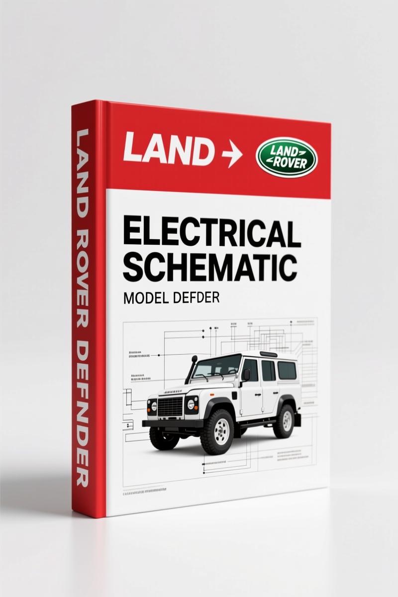
Land Rover Defender 2008 Electrical Schematic – Factory Wiring Diagrams
Original price was: $18.82.$11.99Current price is: $11.99.
OEM Land Rover Defender 2008 Electrical Schematic – 84 pages of factory wiring diagrams for LHD models. Official Land Rover publication.
Description
Land Rover Defender 2008 Electrical Schematic – Factory Wiring Diagrams
I’ve been turning wrenches in San Antonio for twenty-eight years. ASE Master, six bays, and I’ve seen more botched wiring jobs than I’ve had hot dinners. The problem with aftermarket wiring diagrams is they leave out the splice locations, the ground distribution points, and the exact pinouts that keep a Land Rover Defender 2008 Electrical Schematic working right. This is the factory document. Printed by Land Rover in August 2008, publication part number JLR 13 30 21_2E. Eighty-four pages of the real thing – not a reprint, not a scan of a scan. Straight from the OEM.
If you’re chasing a no-start on a Defender LHD with VIN 751063 and beyond, or you’ve got a trailer socket that’s dead, or the ABS light won’t clear – this is where you start. The manual is broken into sections that match the actual vehicle subsystems, not some generic grouping. You get the circuit sheets for anti-lock control, starting system, electronic engine controls for the D4, climate control, auxiliary climate control (windshield heater, rear window heater, non-AC), instrument cluster, horn, clock, battery mounting and cables (header joints, battery junction box, splices, ground distribution), information and entertainment, exterior lighting (rear fog guard lamps, turn signals, trailer socket, stop/reverse, headlamp levelling, head/side lamps), interior lighting, module communications network (diagnostic socket), antitheft system (active and passive), seating (heated front), glass frames and mechanisms (window lift), instrument panel and console (cigar lighter), and wipers and washers (rear and front). That’s the table of contents. That’s the job.
Anti-Lock Control and Starting System: Factory Diagrams
Section 206-09 covers the anti-lock control unit. If your Defender’s ABS modulator is acting up or the wheel speed sensors are giving you erratic readings, you need the factory pin assignments and ground locations. Section 303-06 goes into the starting system – starting and charging for the D4 engine. Page 5 of the manual opens the ABS circuit. Don’t guess which wire is the pump motor feed. The OEM drawing shows it with the correct wire gauge and connector view. Pair this with Land Rover Defender MY2007 Workshop Manual for the removal and replacement steps.
Electronic Engine Controls – D4: What You Need to Trace
Section 303-14 is devoted to the electronic engine controls for the D4. This covers the ECM, sensors, actuators, and the engine harness. I’ve had guys bring me Defenders where the crank sensor signal was missing because someone used a generic diagram and pinned the connector backwards. The factory circuit sheet tells you the exact cavity numbers and wire colors. No ambiguity. Page 9 of the PDF shows the D4 engine control schematic. This is the one to print and tape to your toolbox.
Climate Control and Auxiliary Systems: Heater and Washer Wiring
Sections 412-01 and 412-02 cover the climate control and auxiliary climate control. The windshield heater, rear window heater, and the non‑air‑conditioning setup all have their own dedicated circuit sheets. If your rear wiper isn’t working, go to section 50116 – wipers and washers (rear and front). The wiring for the washer pump and intermittent controller is right there. No need to reverse‑engineer a harness. For a deeper dive into all electrical systems, check Land Rover Defender Electrical Reference Library.
Exterior and Interior Lighting Diagnostics
Sections 41701 and 41702 cover exterior and interior lighting. The rear fog guard lamps, turn signal indicators and hazard flashers, trailer socket, stop and reverse lamps, headlamp levelling, and head/side lamps are all broken out individually. If your trailer lights are intermittent, the factory diagram shows the splice points and the trailer socket pinout. Interior lighting includes the dome lights, map lights, and footwell lamps. The ground distribution is shown in section 41401 – battery mounting and cables. That section also includes the battery junction box, splices, and ground distribution. Without this, you’re stabbing in the dark.
Module Communications Network and Diagnostic Socket
Section 41800 details the module communications network, including the diagnostic socket. The Defender uses a CAN bus system. If you’re having trouble communicating with the ECU or ABS module, you need to know which pins on the OBDII connector carry the data lines. The factory schematic shows the bus topology and termination. This is not something you can infer from a generic wiring book. The manual also covers the antitheft system (section 41901) – both active and passive – which can prevent the vehicle from starting if the wiring is disturbed. I’ve seen technicians spend two days on a no‑crank that turned out to be a broken wire in the passive immobiliser circuit. One look at page 20 of this schematic would have saved the whole job.
Why Factory Schematics Beat Aftermarket Diagrams
I’ve tested aftermarket manuals. They often get the wire colors backwards for the Defender, especially for the LHD models. The factory publication is printed by Land Rover Technical Communications, with approval from the Royal household, and updated for the 2008 model year. Every circuit sheet is drawn to the same standard. Splices are labeled with numbers that tie back to the ground distribution. The Automotive Industry Overview will tell you that OEM documentation is the only reliable source for complex electrical systems. The Automotive Battery diagram in this manual shows the exact cable routing and fusible link locations. Don’t trust third‑party “rewritten” versions.
7 Systems That Need This Schematic
Here’s what you can diagnose with this factory electrical schematic:
- ABS/antilock control – modulator, sensors, and pump relay
- Starting and charging – D4 starter circuit, alternator sense wire
- Electronic engine controls – ECM power, grounds, injector wiring
- Climate control – HVAC blend door actuators, blower motor
- Exterior lighting – turn signals, brake lights, trailer plug
- Interior lighting – all dome and reading lamps
- Antitheft system – passive immobiliser, alarm module
Each system has its own dedicated circuit sheet. You can trace a short from the battery to the bulb in about fifteen minutes if you know how to read the diagram. The manual also includes the abbreviations list (section 004) and instructions on how to use the publication (section 005).
FAQ
- Does this manual cover the trailer socket wiring?
- Yes. Section 41701 includes the full wiring for the trailer socket, including the stop, turn, tail, and reverse circuits.
- What pages contain the ABS control module diagram?
- The ABS circuit starts on page 5 of the PDF. The system is covered in section 206‑09 with full pinouts and ground locations for the LHD Defender.
- Is this the same manual Land Rover dealers use?
- It is the official Land Rover publication (part number JLR 13 30 21_2E) produced by Technical Communications in 2008. Dealers use the same electronic source material, but this is the exact PDF they reference. It is not a simplified version. Land Rover Defender 300Tdi 1996 Workshop Manual covers an older engine, but for electrical diagnostics on the 2008 model, this 84‑page schematic is the authoritative factory document. I’ve used it myself on a 2008 Defender that came into my shop with a dead instrument cluster – traced the fault to a corroded splice in the battery junction box in under an hour.
- Can I use this for a 2007 Defender?
- This manual is specifically for Defender LHD models from VIN 751063 onward, which corresponds to the 2008 model year. Earlier models may have different wiring layouts. Always verify by VIN.
Eighty-four pages of factory-correct wiring diagrams. No guesswork, no aftermarket approximations. The Land Rover Defender 2008 Electrical Schematic is the document you print, laminate, and keep on your workbench. Access the Factory Manual right now and start tracing wires like you’ve been doing it for thirty years.
Additional information
| Brand | Land Rover |
|---|---|
| Language | English |
2 reviews for Land Rover Defender 2008 Electrical Schematic – Factory Wiring Diagrams
You may also like…
-
Sale!
Land Rover Defender 1996 Workshop Manual – Factory Specs for 300Tdi
Original price was: $63.20.$40.00Current price is: $40.00. -
Sale!
Land Rover Defender Workshop Manual – 1213 Pages of Factory Specs
Original price was: $62.80.$40.00Current price is: $40.00. -
Sale!
Land Rover Defender 2007 Electrical Schematic – 338-Page OEM Circuit Data
Original price was: $53.20.$40.00Current price is: $40.00. -
Sale!
Land Rover Freelander 2003 Wiring Diagram – Factory Electrical Schematics
Original price was: $58.95.$45.00Current price is: $45.00.
Related products
-
Sale!

Technical Manual – International DT 530 & HT 530 (118 Pages)
Original price was: $37.00.$25.00Current price is: $25.00. -
Sale!

Acura Integra 1998 Service Manual – 1891 Pages Factory OEM Documentation
Original price was: $31.75.$25.00Current price is: $25.00. -
Sale!

1992 Electrical Schematic – OEM Wiring Diagrams for International 1000-3800
Original price was: $24.48.$18.00Current price is: $18.00. -
Sale!
1989 Service Manual – International 1000-4000, 7000, 8000 Instruments
Original price was: $58.80.$40.00Current price is: $40.00.
gearhead88 –
I am so happy with this manual. The text is searchable and easy to navigate. Contains detailed wiring diagrams for Land Rover. Great value for money.
John S. –
Highly recommended! The scan is high-quality and easy to navigate. A must-have for any Land Rover Rover DIYer doing maintenance. Saves me so much dollars.