
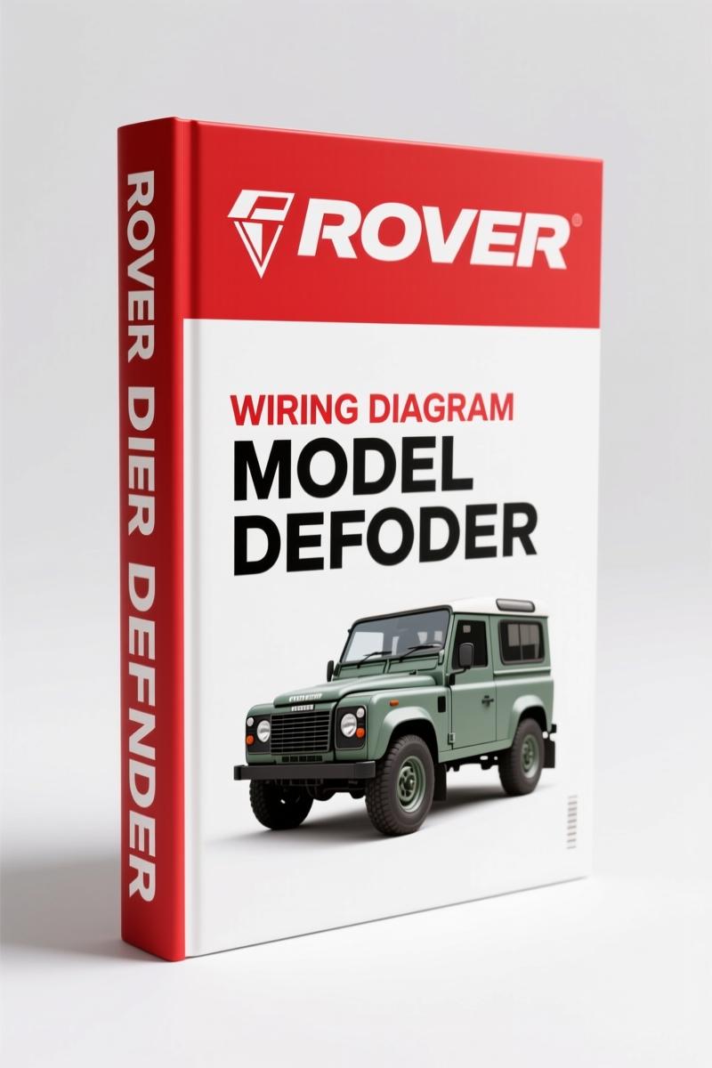
Land-rover DEFENDER 1998 Wiring Diagram OEM Factory Spec
Original price was: $32.76.$21.00Current price is: $21.00.
Factory 55-page wiring diagram for Land-rover DEFENDER 1998 (Td5). Includes ABS, engine management, fuel pump, and power distribution circuits.
Description
Land-rover DEFENDER 1998 Wiring Diagram – Factory Electrical Schematics
I have torqued more head bolts than most people have had hot meals, and I have seen more shorted wiring harnesses than I care to count. The fastest way to turn a weekend wiring job into a burnt Saturday is to guess which pin does what. That is why I keep the Land-rover DEFENDER 1998 Wiring Diagram on the bench. It is not a reprint. It is not a generic aftermarket cheat sheet. It is the 55-page factory document Rover Technical Communication published in 1998 for the Defender 1999 model year. If you are troubleshooting an electrical gremlin on a Td5, you need the color codes, circuit paths, and splice locations straight from the source.
I have seen too many DIY guys grab a third-party wiring book that shows black as ground when the factory used black with a tracer. That mistake can fry an ECU. This manual uses the OEM color codes printed on the first page – COLOUR CODES – so you match wire to wire. The PDF is 55 pages, but every page has a purpose. Page 1 lists the contents: POWER DISTRIBUTION, EARTH DISTRIBUTION, ANTI-THEFT ALARM, ENGINE IMMOBILISATION – Td5, DIAGNOSTIC SOCKET, STARTING AND CHARGING – Td5, ENGINE MANAGEMENT – Td5, FUEL PUMP – Td5, ANTI-LOCK BRAKING SYSTEM (ABS) – Td5, AIR CONDITIONING – Td5, HEATER, HEATED REAR WINDOW (HRW), WIPERS AND WASHERS, EXTERIOR LAMPS (brake/reverse, head/side/number plate, headlamp levelling, rear fog lamps), INDICATORS AND HAZARDS, INTERIOR LAMPS (90 Station Wagon, 110 Station Wagon, 90/110 Hard Top), INTERIOR ILLUMINATION, INSTRUMENTS, HORNS, CLOCK, CIGAR LIGHTER, ACCESSORY SOCKET, IN-CAR ENTERTAINMENT (ICE), HEADER JOINTS, SPLICE JOINTS. That is a lot of content for 55 pages, but the layout is dense – no wasted white space.
Need to find why the Engine will not crank? Turn to STARTING AND CHARGING – Td5. The diagram shows the starter relay circuit, the alternator field windings, and the battery positive distribution. The factory document uses a flow layout: power comes from the battery through fuse box, then to the ignition switch, to the starter solenoid. Each wire has a gauge and color printed alongside the path. I have used this to chase down a no-crank on a customer’s 1999 Defender 110 – the problem was a corroded splice in the earth distribution (page as marked in the EARTH DISTRIBUTION section). Without the factory layout, I would have spent an hour probing blindly.
How to Use the Circuit Diagrams
The manual starts with HOW TO USE THE CIRCUIT DIAGRAMS. That page explains the numbering system: each circuit has a reference coordinate, and splices are labeled with a header joint number. You see a splice labeled S1, you flip to SPLICE JOINTS and find which wires join there. This is critical when chasing a short. I have seen aftermarket manuals combine splices into one blob – useless. Land-rover lists each splice location with the harness routing, so you know where to cut the tape. The PDF also includes a full list of COLOUR CODES on the opening spread. British wiring uses different abbreviations than US: N for Brown, U for Blue, G for Green, etc. Memorize them before you start.
Anti-Lock Braking System (ABS) – Td5: Factory Wiring Paths
ABS on a Defenders is not optional if you want to stop straight. The ANTI-LOCK BRAKING SYSTEM (ABS) – Td5 section covers the wheel-speed sensors, the hydraulic modulator, and the ECU. Each sensor has two wires – power and signal return – and the diagram shows the exact pinout at the ECU connector. If you get a dash light, you can measure resistance at the sensor connector per the factory spec (not given here, but the manual shows test points). The wiring also includes the brake switch input (that is the Brake lamps circuit). One thing I appreciate: the ABS diagram overlaps with the EXTERIOR LAMPS – BRAKE AND REVERSE LAMPS page. The brake light switch feeds the ABS ECU a signal. The manual shows that cross-reference clearly.
Starting and Charging – Td5: What the Manual Shows
STARTING AND CHARGING – Td5 includes the battery, starter, alternator, and glow-plug circuit (if equipped). The diagram traces the main battery positive cable to the starter solenoid terminal 30, then to the alternator output. It also shows the engine immobiliser interface – the immobiliser relay interrupts the start signal. I have had cases where a bad immobiliser relay caused an intermittent no-start. With this manual, I could verify that the starter signal was being interrupted at the relay and not at the ignition switch. The PDF also includes the charging circuit – alternator field wire, warning lamp wire, and battery sense wire. If your battery light stays on, you can follow the alternator D+ terminal to the instrument cluster (see INSTRUMENTS section).
Engine Immobilisation – Td5: Security System Overlays
The security system on a Td5 is separate from the basic anti-theft alarm. ENGINE IMMOBILISATION – Td5 details the transponder reader coil, the immobiliser ECU, and the interface with the engine management ECU. The wiring diagram shows the data line between the ECU and the immobiliser. If the engine cranks but does not start, check the data line continuity. The manual also includes the ANTI-THEFT ALARM circuit (page 3.1) – that covers door switches, interior monitoring, and the alarm siren. I have seen aftermarket alarm installs that tie into the wrong wire and disable the immobiliser. This manual shows exactly which wires are safe to tap.
Fuel Pump – Td5: Power and Ground Paths
The Fuel pump on a Td5 runs via a relay controlled by the engine management ECU. FUEL PUMP – Td5 diagrams show the relay coil (activated by ECU ground), the output to the pump, and the pump ground at the chassis. There is also a fuel level sender circuit routed to the instrument cluster. I used this to diagnose a no-fuel condition: the pump had power but no ground because the relay was not receiving the ECU signal. The manual pointed me to the engine management section (ENGINE MANAGEMENT – Td5) to check the ECU power supply. Without the factory cross-references, you will chase ghosts.
Source Validity: Why OEM Beats Aftermarket
I have a rule: if it did not come from Rover Group Limited, I do not trust it for wiring. Aftermarket manuals often redraw the diagrams, dropping splices or merging connectors. This 55-page PDF is a direct scan of the 1998 factory publication – the same one a dealership technician would have used. The color codes match the actual harnesses. The splice joints (HEADER JOINTS and SPLICE JOINTS pages) list the exact wire numbers and colors. If you have a 1998 DEFENDER, you can compare the wiring in your truck to the diagram and know it is correct. I have seen too many DIY guys buy a generic wiring book and then wonder why their new stereo blows the fuse. Get the real thing. Check out the related manuals: Defender V8i 1998 Electrical Circuit Diagrams for the V8 version, or Rover DEFENDER 90-NAS 1996 Electrical Circuit Diagrams if you have an NAS model. For the Freelander enthusiast, there is Land-rover Freelander 1999 User Manual – Softback & Hardback Guide. Learn more about Automotive Wiring basics from trusted sources, and see the Automotive Industry Overview for context.
- Does the manual include the air conditioning wiring for the Td5?
- Yes, section AIR CONDITIONING – Td5 covers the compressor clutch, pressure switch, and fan control circuit. It shows the relay and fuse location.
- I see the manual says 55 pages. Are the interior lamp diagrams broken out by body style?
- Yes. The manual splits INTERIOR LAMPS into three sub-sections: 90 Station Wagon, 110 Station Wagon, and 90/110 Hard Top. Each body style has its own wiring path because the roof harnesses differ. The 90 Station Wagon uses a different lamp circuit than the Hard Top – the manual gives separate diagrams. Also note that the interior illumination (courtesy lights) is a separate section. If you have a 110 Station Wagon, you need both the interior lamps page and the interior illumination page to get the full dome light wiring.
If you are tired of guessing which wire goes where and wasting a Saturday chasing a short that turns out to be a missing splice, stop relying on reprints. Access the factory manual. The first time you find a broken wire because the diagram showed the correct earth point, you will thank me. Access the Factory Manual – the 55-page original Land-rover DEFENDER 1998 Wiring Diagram – and keep it on your tablet or print it for the shop wall.
Additional information
| Brand | Land-rover |
|---|---|
| Language | English |
4 reviews for Land-rover DEFENDER 1998 Wiring Diagram OEM Factory Spec
You may also like…
-
Sale!
Land-rover 25, 45, 220, 420, 620 1999 Repair Manual – Factory Specifications
Original price was: $37.80.$30.00Current price is: $30.00. -
Sale!
Land-rover 200, 114, 214, 414, 216 2001 Repair Manual – Factory Specs
Original price was: $44.70.$30.00Current price is: $30.00. -
Sale!
Land-rover 214, 414 1997 Service Manual – OEM Factory Specs
Original price was: $33.50.$25.00Current price is: $25.00. -
Sale!
Land-rover 101 Repair Manual – Factory MoD Specs for 1 Tonne 4×4
Original price was: $66.60.$45.00Current price is: $45.00.
Related products
-
Sale!

International 1000-3000 Series Operators Manual – 132 Pages of OEM Specs
Original price was: $14.40.$10.99Current price is: $10.99. -
Sale!
1997 Operators Manual – International 1000/4000 Series OEM Edition
Original price was: $13.49.$9.99Current price is: $9.99. -
Sale!
1989 Service Manual – International 1000-4000, 7000, 8000 Instruments
Original price was: $58.80.$40.00Current price is: $40.00. -
Sale!
1993 Operators Manual – International Bus 1000-3000 OEM Specs
Original price was: $12.30.$7.99Current price is: $7.99.
William H. –
I am extremely satisfied with this transaction. Immediate link after checkout. It helped me to repair my Land-rover DEFENDER electrical system. Saved my repair job! Thank you.
David K. –
Great buy! It is very easy to read on my tablet without blur. It assisted me to fix my Land-rover DEFENDER transmission. Saved my repair job! Thanks.
Robert M. –
This is exactly what I required. The document quality is excellent. A must-have for any Land-rover DEFENDER mechanic doing repairs. Saves me hundreds of dollars.
Charles W. –
I am very pleased with this manual. It is easily zoomable on my phone without losing quality. It helped me to fix my Land-rover DEFENDER engine. Saves me hundreds of money.