
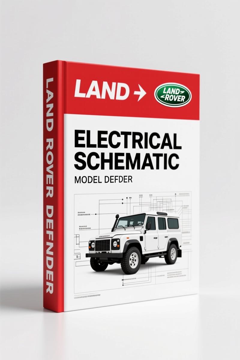
Land Rover Defender 1996 Electrical Schematic – Factory Wiring Data
Original price was: $24.48.$16.00Current price is: $16.00.
Factory OEM electrical schematic for Land Rover Defender 1996 – 32 pages with power distribution, earth paths, and circuit diagrams.
Description
Land Rover Defender 1996 Electrical Schematic
You’ve got a Land Rover Defender 1996 Electrical Schematic problem staring you down – a dead brake lamp circuit, an immobiliser that locks you out, or a heater that blows cold. Pull a generic diagram from the web and you’ll be chasing ghosts. I’ve wasted hours on aftermarket garbage that didn’t match the pinouts. This 32-page OEM booklet from Rover Group (1996) is the real deal. It’s the same binder the factory techs had on the bench. No translation errors, no missing wires. Every colour code, every splice, every connector pin is factory-specified.
OEM Color Codes and Wire Attributes
Page 2 of the manual lists every wire colour used on the Defender – black, green, pink, light green, brown, orange, purple, red, slate (grey), blue, white, yellow. Each has a two-letter code. More important: the diagrams include wire gauge in square millimetres and wire length in millimetres for the power and earth sections. If you’re repairing a harness, that info tells you exactly what wire to grab and where the splice is buried. Aftermarket diagrams never give you wire lengths.
What Does the Power Distribution Section Cover?
Power distribution starts on page 3 with a full diagram from battery to engine and passenger compartment fuse boxes. The manual also shows internal fuse box circuitry – not just which fuse feeds what, but the header joints and splices inside the harness. You get tables listing each splice (e.g., A82, C574) with wire colours and distances. Use those to narrow down a fault without peeling the whole loom. This is how you isolate a short without guessing.
3 Critical Systems: Charging, Starting, Immobiliser
The “Charging and Starting” section splits into 300TDi and V8 variants. That’s two separate diagrams – don’t mix them up. The V8 uses a different starter relay and alternator field wiring. The engine immobiliser circuit is shown in its own section, covering both immobilised and non-immobilised versions. If your Defender won’t crank and the immobiliser light is flashing, you go straight to that page. No scrolling through 50 pages of generic theory.
Use the Headers and Splices Tables Correctly
Page 3 explains how to read the header and splice tables. Each header joint is identified by connector number and pin – e.g., C289-1 means connector 289, pin 1. Splices get an alphanumeric prefix. When diagnosis points to an open circuit in a harness branch, you reference the splice table to find which wires join at that point. Then measure from the shortest wire to locate the joint. That’s the factory method I use on every electrical job.
Exterior Lamps: Brake, Reverse, Head, Side, Tail, Rear Fog
The “Exterior Lamps” chapter lays out brake and reverse lamps together, then head/side/tail, then rear fog. The brake lamp circuit runs through the stop-light switch and connects to the brake pedal – if you’re retrofitting LED bulbs, you need the correct wire colour (red-green, page 2 code RG) and the right splice point. The manual shows each lamp’s earth return. Don’t trust a forum post telling you to ground it to the chassis; find the factory earth point on the diagram.
Interior Lamps: Four Immobilisation Variants
Interior lamps get four separate diagrams depending on body style and immobilisation – 90 Hard Top (non-immobilised), 90/110 Hard Top (immobilised), 110 Truck Cab, 90/110 Station Wagon & 130 Crew Cab. If you have a 130 and guess the 90 diagram, you’ll miswire the door switches. The manual labels each variant clearly. Same for interior illumination, instruments, clock/cigar lighter, and in-car entertainment – each has its own circuit.
Earth Distribution: Why It Matters
A separate “Earth Distribution” section shows the ground paths for every system. Bad earths cause more electrical faults than failed components. The manual lists each earth point by location and wire colour. For example, the engine earth strap termination is shown with its gauge and routing. You can trace a voltage drop back to a corroded ground terminal in minutes rather than hours.
FAQ
- Does this manual cover the V8 engine?
- Yes. The “Charging and Starting” section has separate diagrams for 300TDi and V8. The V8 diagram includes starter and alternator wiring specific to that engine.
- Can I use this for a 1997 Defender?
- No. This is a 1996 publication. Land Rover changed wiring harness layouts and immobiliser systems for 1997. You need the corresponding year-specific schematic. Check our Land Rover Defender MY2007 Workshop Manual for later models.
- What page lists the brake lamp circuit?
- Brake and reverse lamps are covered under “Exterior Lamps”. Page numbers vary by binding, but the section runs after the head/side/tail lamp diagrams. Use the colour codes on page 2 to identify the brake feed wire (red-green).
- Are the diagrams in colour?
- The original manual uses colour codes printed on black-and-white lines – each wire is labelled with its colour abbreviation (e.g., N for black, R for red). A full colour-code table is on page 2. For true colour reproduction, the digital file preserves the original layout.
I don’t stock aftermarket reprints. This is the original 1996 Rover Group electrical schematic – 32 pages, factory binding, scanned from a dealer library copy. If you’re rebuilding a Defender harness or chasing a ghost circuit, you need the real thing. Access the Factory Manual and get the diagrams that match your truck. Pair it with the Land Rover Defender Electrical Reference Library for diagnostic theory and the Land Rover Defender 300Tdi 1996 Workshop Manual for engine mechanicals. For a broader look at the Automotive Industry Overview of electrical standards, that’s background – but this schematic is the tool you use on the bench. Also keep in mind the Automotive Battery health when testing circuits; a weak battery can mimic a wiring fault.
Additional information
| Brand | Land Rover |
|---|---|
| Language | English |
4 reviews for Land Rover Defender 1996 Electrical Schematic – Factory Wiring Data
You may also like…
-
Sale!
Land Rover Defender Workshop Manual – 1213 Pages of Factory Specs
Original price was: $62.80.$40.00Current price is: $40.00. -
Sale!
Land Rover Freelander 2003 Wiring Diagram – Factory Electrical Schematics
Original price was: $58.95.$45.00Current price is: $45.00. -
Sale!
Land Rover Defender 1996 Workshop Manual – Factory Specs for 300Tdi
Original price was: $63.20.$40.00Current price is: $40.00. -
Sale!
Land Rover Defender 2007 Electrical Schematic – 338-Page OEM Circuit Data
Original price was: $53.20.$40.00Current price is: $40.00.
Related products
-
Sale!

Service Manual – International HS 2.8L Engine – 130 Pages of Factory Specs
Original price was: $56.40.$40.00Current price is: $40.00. -
Sale!

International 1000-3000 Series Operators Manual – 132 Pages of OEM Specs
Original price was: $14.40.$10.99Current price is: $10.99. -
Sale!
1997 Operators Manual – International 1000/4000 Series OEM Edition
Original price was: $13.49.$9.99Current price is: $9.99. -
Sale!

2005 Parts Catalog – International NGD 3.0 L Engine (77 pages)
Original price was: $44.70.$30.00Current price is: $30.00.
pro_mechanic –
I am so happy with this transaction. The document is high resolution. A must-have for any Land Rover Rover owner doing repairs. I will definitely buy again.
James L. –
Great buy! It is easily zoomable on my phone without blur. Every wiring layout is included for Land Rover Rover. Great value for money.
diy_master –
Great factory service manual. The text is searchable and easy to navigate. Contains precise wiring diagrams for Land Rover. Great value for money.
Richard G. –
Superb resource! It is easily zoomable on my phone without blur. Contains clear schematics for Land Rover. I will definitely buy again.